- Products & Capabilities

- About
- Resources
A Guide to Testing Capacitors on PCB


Capacitors are crucial in circuits for storing energy. Testing methods include in-circuit and out-of-circuit using digital multimeters, ESR, and LCR meters. Proper testing ensures reliability and prevents malfunctions.
Capacitors are perhaps the most critical parts of an electronic circuit, given their role of storing and releasing electrical energy. Comprehension of how to test the capacitors on a Printed Circuit Board is the center of diagnosing issues in circuits or ensuring component reliability. In this paper, the types of capacitors will be further elaborated upon, along with functionality and a number of ways to perform testing: both in-circuit and out-of-circuit testing by means of professional techniques.
Overview of Capacitors
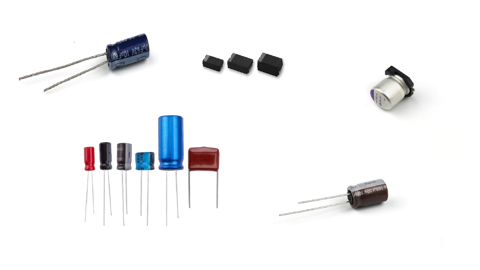
What is a Capacitor?
A capacitor is an electronic device that stores electrical energy in the form of an electric field. It consists essentially of two conductive plates separated by a dielectric medium; the dielectric serves to increase the charge capacity of a capacitor. Capacitors can be manufactured in many different shapes and sizes depending upon their intended application. Common materials for dielectric include ceramic, mica, glass, and air.
How Does a Capacitor Work?
Capacitors work on the principle of storing electric charge on their plates whenever a voltage is applied across them. One plate becomes positively charged, while the other plate gains negative charge, and the charge remains there unless the capacitor is subjected to a secondary circuit. As opposed to batteries, which store electrical energy through chemical means, capacitors store electrical energy directly.
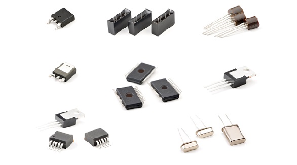
Types of Capacitors
Ceramic Capacitors: Use a ceramic dielectric.
Polymer Capacitors: Use of conductive polymer as an electrolyte.
Paper and Film Capacitors: These use paper or film as dielectrics
Super Capacitors: These have very high capacitance values
Shunt Capacitors: These are used for the correction of power in the power system.
Series Capacitors: These improve the capacity and stability of transmission by acting like inductive compensation to the transmission lines.
Testing Methods of Capacitors on a PCB
Capacitor testing on a PCB may be done in several ways, each applying to different situations and depending on the level of precision required.
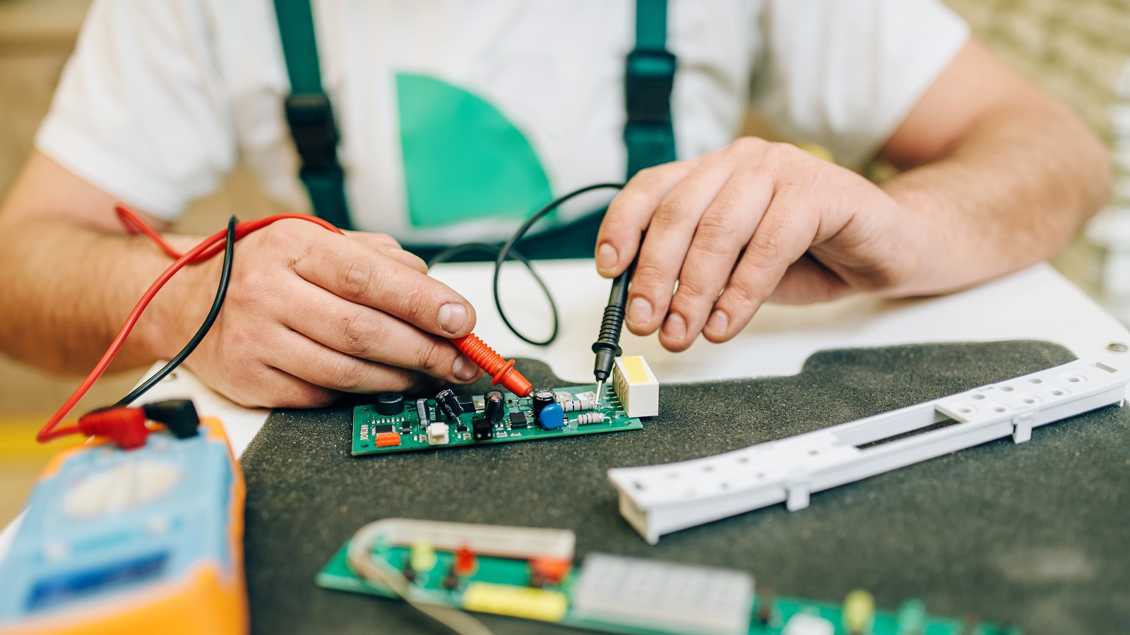
In-Circuit Testing
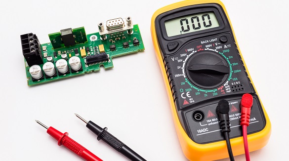
1. Using a Digital Multimeter
- Set Multimeter to Capacitance Mode: First things first-make sure the configuration is proper in your multimeter.
- Discharge the Capacitor: Use a resistor in order to safely discharge the capacitor to avoid shocks or multimeter damage.
- Connect Multimeter Leads: Connect the test probes to the leads of the capacitor. Remember, in-circuit testing may be deceiving because of other components.
- Read the Capacitance: Take note that this reading should be compared to the value that is rated for that capacitor. Large deviation could mean a problem.
2. Using an ESR (Equivalent Series Resistance) Meter
- Put ESR Meter in Test Mode: Set it up for testing with correct lead connections.
- ESR Meter Leads Connect: Connect the probes to the capacitor leads, as often the ESR can be tested in-circuit.
- Read ESR Value: Compare with standard values for that capacitor type and capacitance. High ESR suggests degradation.
Out-of-Circuit Testing
When higher accuracy is required, the capacitor is often better to be removed for testing.
1. Using a Digital Multimeter
Capacitor Removal: Desolder and isolate.
Select Capacitance on Multimeter: Switch into capacitance measurement mode.
Connect Multimeter Test Leads: Connect the probes to the capacitor leads.
Measure Capacitance: Read the measurement versus the expected value. Any deviation from this, normally, means failure.
Read ESR Value: Compare it to standard ranges for acceptability of the capacitor.
3. Using an LCR (Inductance, Capacitance, and Resistance) Meter
Remove the Capacitor: Desolder and isolate it.
Set LCR Meter to Capacitance Mode: Put it in capacitance measurement setting.
Connect LCR Meter Leads: Attach the probes accordingly.
Read Capacitance and ESR: Note both values and compare them against specifications.
Other Methods
Time Constant Method
This method is useful when the value of capacitance is already known.
Setup: The capacitor should be in series with a resistor of known value.
Charge: Apply voltage and measure how long it will take for the capacitor to rise to 63.2% of the applied voltage.
Compare: Using the formula for RC time constant, check the condition of the capacitor.
Using a Voltmeter
Charge the Capacitor: Briefly apply a voltage.
Power Supply Off: The multimeter then measures the voltage across the capacitor.
Read and Compare: A reading close to the input voltage reflects the good health of the capacitor.
Safety Precautions
Capacitor Discharge: Capacitors are always to be completely discharged before every test; otherwise, they will definitely cause an electrical shock along with multimeter damage.
ESD Precautions: Capacitors should be handled with due electrostatic discharge precautions so that their sensitive components are not damaged.
Conclusion
The testing of various kinds of capacitors on a PCB applies a range of tools, including digital multimeters, ESR meters, and LCR meters. Each test method is applied correspondingly either to a quick in-circuit test or a highly accurate measurement out of circuit. Being able to recognize the types of capacitors, their function, and how they are tested will ensure the reliability and performance of your PCBs to maintain the overall integrity of electronic devices.
Capacitors are critical components; hence, great care should be exercised in their handling and testing to avoid malfunction. Proper test methods will ensure reliable operation of capacitors in energy storage applications, signal decoupling, or other power conditioning applications.
Hot Tags:
Contact us

If you can't find what you're looking for, please contact us.

 2024/08/28