Common Circuit Board and Component Failures
Routine inspections and proper maintenance of capacitors and resistors in PCBs reduce failures, prolong device lifespan, and lower maintenance costs.
Printed circuit boards basically form the backbone of most electronic devices, enabling a structured connectivity among components in electronics. Despite their important role in the functionality of an electronic device, failures have been reported about PCBs and its parts, such as capacitors. Some common failure characteristics, maintenance strategies, and practical troubleshooting techniques are listed here concerning industrial control circuit board capacitors and resistors.
Capacitor Failures on Circuit Boards
Capacitors, whether on motherboards or otherwise, are so crucial in filtering power supply and voltage regulation. The failure of these devices is actually one of the most common problems in electronic equipment. Electrolytic capacitors, especially, will have the highest failure rates under some environmental influence, coupled with their chemical nature.
Common Characteristics of Capacitor Failures
Capacitance Loss: The capacity of a capacitor to store charge is lost, which is manifested either by the failure of capacitance or by an all-out loss.
Leaks/Shorts: These are very potential causes of electrical malfunction and hence have to be taken care of immediately.
Physical Anomalies: Swollen/leaking capacitors that are located near any source of heat are its sure-shot symptoms for imminent failure.
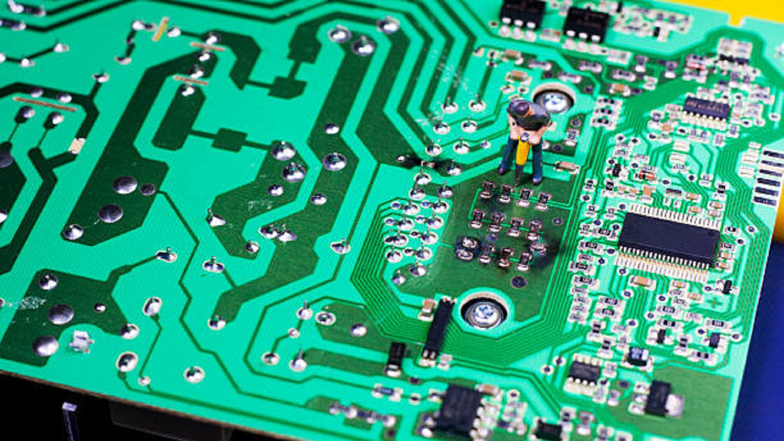
Maintenance and Solutions
Routine Checks: Swelling or leakage in all the capacitors, but those around heat sinks and high-power parts, indicate any failure.
Replace them with high-quality capacitors from reputable companies like Rubycon or Black Diamond. Replace the critical ones like a capacitor on a motherboard.
Thermal Management: There should be some good heat dissipation mechanism in order to extend the life span of the capacitor.
Resistance Component Failures
Resistors are involved in current limiting and voltage division. Generally less common to fail when compared to capacitors, resistors can also go open circuit and cause significant upsets in circuit operation.
Features of Resistor Failures
Open Circuit: Most common type-in which the resistor no longer conducts electricity.
Physical Damage: Burned or blackened resistors are a dead giveaway, especially on low values of resistance.
High-Resistance Resisters: The highly resistant resisters may not show overt symptoms at the time of failure but can be successfully identified using multimeter
Maintenance and Solutions
Visual Examination: There can be discoloration or evidence of burn due to excessive heat generation .
Test using Multimeter: Multimeter measures the value of resistance. Extremely High reading much larger than the rated values is indicative of the damages to the component.
Special Attention to Types That Are Vulnerable: Special interest shall be taken in high-current limiting wire-wound resistors that fail very silently and do not give any visible signs.
Checking Operational Amplifiers
Since operational amplifiers are involved in a very crucial role in the amplification of signals, operational amplifiers need to have much attention paid to their evaluation. The distinction needs to be made between whether it was employed as an amplifier or comparator to troubleshoot accordingly.
Test Techniques
Virtual Short Analysis: When working in a linear mode of operation, opamp inputs-inverting and non-inverting-are expected to have equal voltage levels.
Voltage Testing: If it was operating in comparator fashion, the voltage at the respective input sets will show if it is good or not.
SMT Components Testing
SMT components on the PCB are small in size and hence need to be handled precisely. Modified multimeter probes using fine needles for testing will avoid accidental short circuits, and when there is a protective coating, precision accuracy can be got. It ensures readings of the finest detail.
Power Supply and Connection Issues
Faulty isolation of short circuits in the power supply lines is done with variable power supplies offering fault isolation in a non-destructive way, to safely identify faulty components. Cleaner, well-secured connections with eraser-treated gold fingers also allow an increase in the reliability of contact in industrial configurations.
Environmental Influences and Electrical Failures
Dampness and dust lead to accelerated wear of hardware and to diffuse electrical failures.Active cleaning and care on the board reduce risks concerning the surroundings.
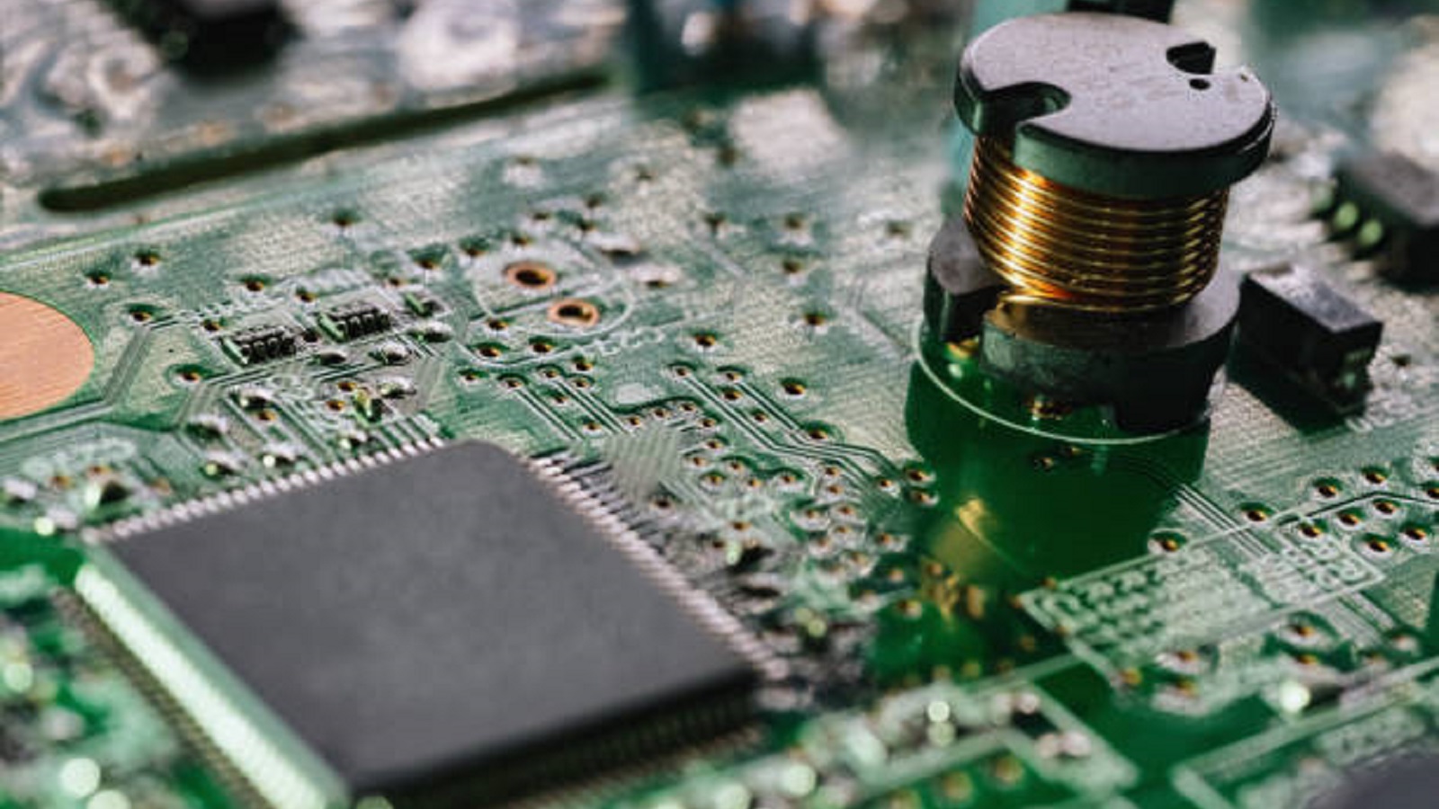
The ability to identify the characteristics of capacitor failures in printed circuit boards, as well as subtlety regarding component maintenance, will enable the electronic engineer and technician to further prolong the lives of PCBs while maintaining device reliability. The overall effect of routine inspections, correct component selection, and appropriate troubleshooting will be the reduction of consumer and industrial electronic system downtime while bringing down maintenance costs.
Hot Tags:
Contact us

If you can't find what you're looking for, please contact us.
Article
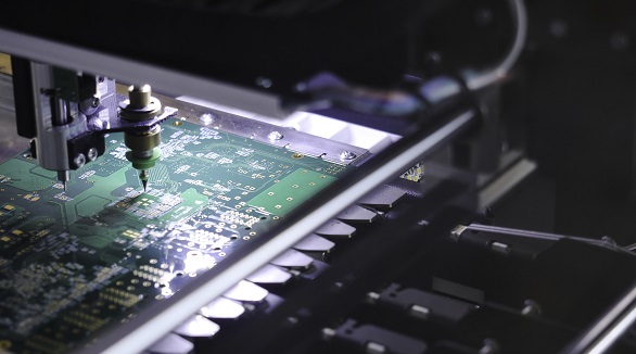
Reflow soldering is vital for PCB assembly but faces challenges like solder bridging, tombstoning, and voiding. Effective solutions include optimized stencil design, thermal profiling, and precise component placement.
Wave soldering is vital for assembling printed circuit boards (PCBs), aiming to bond electrical components. The process involves passing PCBs over a wave of molten solder to form connections. Common defects include pin/blow holes, solder shorts, poor hole fill, lifted components, excessive solder, solder balling, and solder flags. To address these issues, key factors include proper flux application, controlled preheat temperatures, optimal solder wave settings, and careful material handling. Understanding and managing these factors ensures high-quality, reliable PCB assemblies.
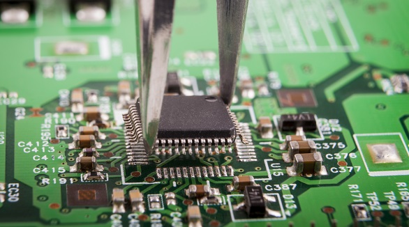
Still, SMT can further feature defects such as solder bridging, cold solder joints, tombstoning, and solder balling. Grasping the very common faults and their solutions is the key toward effective PCB assembly and reducing SMT errors—very much in line with the trend toward PCB miniaturization and higher component density.
