Comprehensive Guide to Test PCB: Ensuring Quality and Reliability
PCB testing ensures quality and reliability by assessing key components like lamination, copper plating, and conductivity. Methods include ICT, FPT, Burn-in, and AOI. Testing reduces bugs, time, cost, and enhances safety.
In the modern context of electronics, Printed Circuit Boards form a very vital part of most applications, ensuring that these PCBs meet design specifications and show high quality necessitates rigorous testing. This article outlines the vital procedures, testing methods, and equipment used in PCB testing, together with the benefits provided by these assessments.
The Importance of PCB Testing
Testing is indispensable in the manufacturing process of PCBs to ensure that it meets requirements and is free of defects. This quality assurance is quite important in maintaining product integrity and reliability to sustain end-user needs.
Key Components Tested in PCBs
Lamination
Testing for peeling resistance to heat/force, since the quality of lamination has an effect on general functionality and the life span of the PCB.
Copper Plating
Quality checking of copper with tensile strength and elongation tests for the best conductivity with good endurance.
Hole Wall Quality
- Ensuring hole walls do not break and crack under operating thermal stress conditions, usually arising during practical applications.
- Solderability
- The ability of the material to wet with solder determines its snugness with the board by means of an appropriate wetting area.
- Electrical Conductivity
- Verifying if the PCB allows the flow of electricity with minimum leakage, which is actually the very reason for its existence.
- Environmental Resistance
- Water absorption tests are carried out to study the resistance of the PCB against humid conditions. Tests for resistance to corrosion and other environmental elements are also conducted.
- Cleanliness
- Humidity and corrosion resistance is key in maintaining its longevity and reliability over variable environmental conditions.
Equipment needed to test a PCB includes:
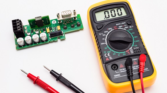
Analog/Digital Multimeter
It measures voltage, current, and resistance on various parameters in order to confirm whether the circuit is working and locates faults in the circuit.
Soldering Gun
It is used to connect the electronics components. The soldering must be strong enough to hold the parts firmly without melting the component.
Desoldering Station
This helps in removing components or correcting previous soldering mistakes. Without causing damage to the PCB or any of the components.
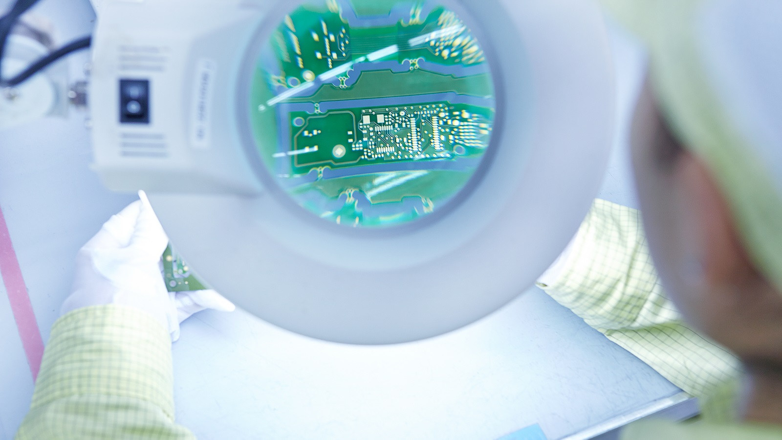
Magnifying Glass
To have a close check at the PCB, allowing for the defects in the form of corrosion or broken connections on the board.

Methods for Testing PCBs
There are various methods to meet different test requirements, as follows:
In-Circuit Test - ICT
Non-destructive tests using customized fixtures and probes for testing electrical connections on printed circuit boards. It normally operates in high volume to identify defects in components with great efficiency.
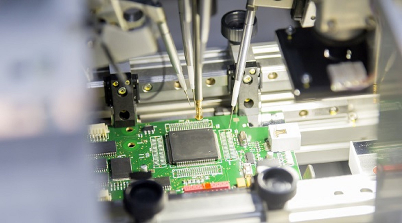
Flying Probe Test
Utilizes mobile probes and no fixed fixture. It offers flexibility in testing complex PCB design for prototype and low volume productions. Slower compared to ICT, cost-efficient, and adaptable.
Burn-in Testing
Extreme conditions are applied to the PCB, much more than the design criteria, in order to determine its weak points and assure its strength under load in heavy stress, which is going to be important for durability.
Functional Circuit Test
Checks the actual performance of the PCB through test signals and output measurements to ensure that all the components are performing their functions accurately. Suitable to identify component imperfections which other techniques may fail to identify.
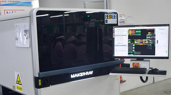
Automated Optical Inspection (AOI)
High-resolution cameras that detect failures in a contactless way due to visual defects and help assure the assembly at many stages.

Visual Test and Functional Test of Power Module
Visual Testing
The first stage which includes physical damage, proper solder joints, proper placement of the component, and no broken traces.
Power Module Testing
Ensures that the proper voltage and current are supplied to the power supply. This usually can be tested by monitoring correct heat generation or checking the general performance of the power module.
Testing I/O and Communication Ports
I/O Ports
Provide proper connectivity and signal integrity to operate input/output interfaces without incidence of short circuits.
Communication Ports
Ensure proper connection and data transfer between them; hence, this is very important for the proper communication with other external components.
Advantages of Testing on PCBs
Bug Identification
Helps to identify the problems in the earliest stage and confirms that the final product will meet the performance requirements.
Time Reduction
The identification of issues in the prototyping stage will reduce the lead time and speed up the process of manufacturing.
Cost Reduction
It eliminates manufacturing faulty products because it reduces waste, which aids in lowering manufacturing costs.
Less Returned Goods
Reduces defects and improves customer satisfaction, and reduces the cost in handling returns.
Increased Safety
Ensures the vital electronic components are reliable and do not pose hazards, such as fire outbreaks or damage to other equipment.
Quality Testing of PCBs with PCBX
PCB testing is an integral part of manufacturing, with a number of key benefits, from ensuring product quality to time and cost savings. In many cases, robust test procedures allow manufacturers to ensure their PCBs perform to criteria and meet customers' expectations, which enhances overall reliability and safety.
At PCBX, we offer the finest prototype and small-volume productions to accelerate your test. Commitment to dependability and accountability ensures the highest level of service for your testing needs in PCBs. For any quotation, do not hesitate to contact us today and enjoy the benefits of superior PCB testing at PCBX.
Hot Tags:
Contact us

If you can't find what you're looking for, please contact us.
Article

A multimeter is vital for electronics, measuring voltage, current, and resistance. This article covers its basic functions, settings, and guides you on PCB testing, ensuring accurate and safe troubleshooting.

As PCB lines and components shrink, traditional visual inspection fails; AOI using DRC and CAD methods is crucial for quality SMT assembly, offering intelligent, accurate inspections.

These SMT PCB assembly methods are involved, ensuring that several defects are detected. This includes the use of Automated Optical Inspection, In-Circuit Testing, and Automated X-ray Inspection. The combination of these methods is beneficial in facilitating an optimal inspection process.