Dielectric Constant in PCBs
The dielectric constant in PCBs affects signal speed, integrity, and impedance, crucial for optimizing high-frequency circuit performance.
The most influencing factors in the design of a printed circuit board are due to the dielectric constant of the applied materials. This property, given by the symbol, is cardinal in the design and functionality of high-speed and high-frequency electronic circuits. Knowledge of the subtleties in the dielectric constant allows the engineer to make a big impact on performance, efficiency, and reliability for electronic devices. This article explains the role of the dielectric constant in PCBs, its importance, types of materials available, and its implications for circuit design.
The dielectric constant, or relative permittivity, is a measure of the relative ability of a material to store electrical energy in an electric field with respect to a vacuum, which has a dielectric constant of 1. In PCBs, this constant helps determine how signals propagate through the circuit board, affecting speed and integrity. It basically quantifies a material's polarizability and influences how the electric field at a microscopic level acts upon that material.
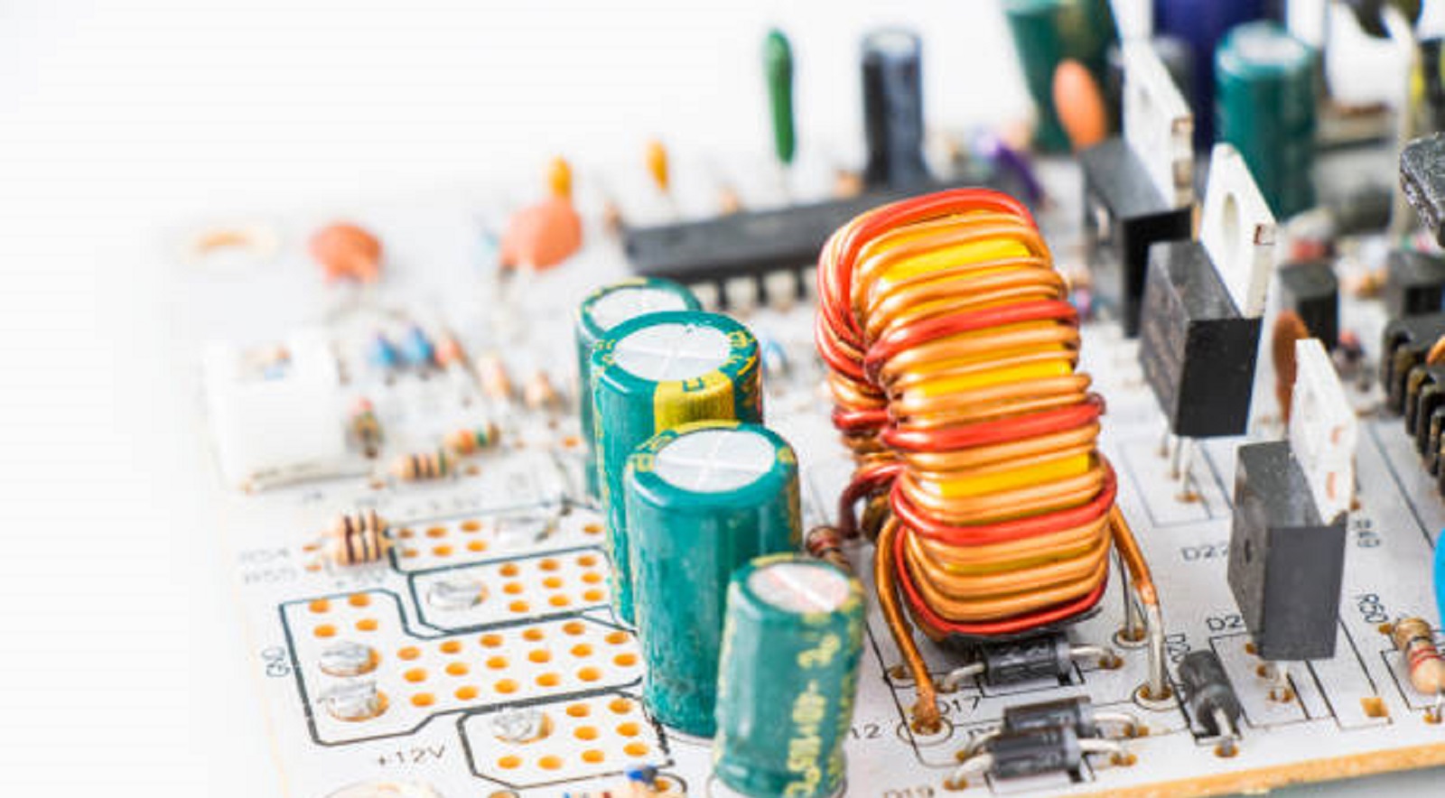
Importance of Dielectric Constant in PCB Design
Signal Integrity
Among the main issues in PCB design is signal integrity, especially when devices have to process at high speeds. The dielectric constant directly influences the velocity of electromagnetic waves through the board. A low value of dielectric constant normally allows faster propagation of signals, hence allowing error-free high-speed digital applications due to induced delays or signal degradation.
Impedance Matching
Impedance matching is important for signal integrity, especially in high-frequency circuits. The dielectric constant is a critical constituent of impedance calculations that determines trace dimensions and spacing. Variations in the dielectric constant will cause impedance mismatches that can result in reflections and loss of data integrity.
Crosstalk Mitigation
Crosstalk-it is the unwanted coupling of signals between adjacent traces-can interfere with signal integrity. Designers can reduce crosstalk, thereby enhancing general signal quality and avoiding electromagnetic interference errors, by selecting dielectric material with appropriate constants.
Physical Design and Layer Stack-Up
The dielectric constant affects the layer stack-up in multilayer PCBs. It specifies the thickness of the dielectric layers, which has to be balanced with performance and manufacturing cost. Proper understanding and application of the dielectric constant ensure that the stack-up design supports both component functionality and physical stability.
Factors Affecting Dielectric Constant
Material Composition: FR-4, ceramic, and PTFE are among the different materials with different dielectric properties, and their differences should be put into consideration when selecting materials for different applications.
Frequency Dependency: The dielectric constant may be frequency-dependent. High-frequency applications may require materials whose dielectric properties are invariant over a range of operating conditions.
Temperature and Environmental Conditions: Temperature changes can alter a material's dielectric constant, which affects circuit performance under various environmental conditions. Design considerations must therefore include thermal management strategies.
Common PCB Materials and Their Dielectric Constants
FR-4
The most common PCB material, FR-4, has a dielectric constant that generally lies in the range of 4.2 to 4.8. While suitable for many general-purpose applications, it may face limitations in high-speed and high-frequency scenarios.
Ceramic
Ceramic materials will have a selection of dielectric constants from approximately 3 to 10. These are particularly popular in RF and microwave applications because of their stability and compatibility with high-frequency applications.
PTFE (Teflon)
PTFE materials, with a dielectric constant of about 2.1, provide the best environments for applications requiring minimum signal loss and high speed. Such stability at high frequencies makes PTFE useful in a number of advanced electronic devices.
Procedure for Measuring Dielectric Constant
Accurate measurement of the dielectric constant, therefore, has a bearing on the reliability and predictability of the performance of the PCBs. Such techniques as split-cylinder resonator, microstrip line analysis, and cavity resonator methods provide precise measurements essential for high-fidelity design and analysis.
Designing with Dielectric Constant in Mind
Material Selection
Selection of material is crucial. Substrates should be selected on the dielectric constant and their alignment to the frequency and the performance requirements of the application. Selection directly determines whether the board can handle the desired electrical performance or not.
Simulation and Testing
Modern simulation tools model the effects of the dielectric constant on signal integrity, impedance, and other performance characteristics. Software platforms, such as that provided by PCBX, enable a designer to predict material behavior and test performance in advance before the need for physical prototyping.
Prototyping
Prototype testing helps confirm the predicted performance and makes modifications to the designs for the selected materials to perform satisfactorily in actual operation. This is an essential step in linking the theoretical design to the practical implementation of the design.
Software Tools
With the inclusion of robust design tools, like Altium Designer, an engineer can effectively simulate and visualize how dielectric constants will affect performance. Such systems will offer impedance calculation, layer stack-up visualization, and signal behavior all in one platform to help empower a designer's decisions.
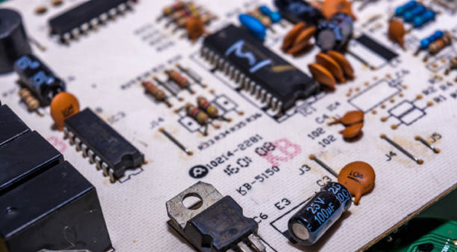
The most crucial factor that would affect everything in PCB design, from signal speeds to thermal performance, is the dielectric constant. A deep understanding of this parameter allows the engineer to optimize circuit performance for the latest electronic applications. As technology advances and the demands for devices that are faster and more reliable continue to increase, control of dielectric properties is vitally important to successful electronic design. At PCBX, we are committed to providing the insight and solutions designers seek in order to utilize these properties effectively and shape the future of electronic systems for years to come. Be it consumer electronics, aerospace, or even telecommunications, control of the dielectric constant opens a whole new dimension in electronic design.
Hot Tags:
Contact us

If you can't find what you're looking for, please contact us.
Article
Castellated pads in PCB design facilitate easy board-to-board connections, enhancing miniaturization, assembly, solder quality, and flexibility for compact modules.
Capacitive circuits store and release energy, stabilize voltage, filter signals, and manage power flow, making them vital for modern electronic systems.
eFuses are advanced PCB fuses that reset automatically, offering fast, precise protection and versatility in electronics, enhancing device safety and reliability.