- Products & Capabilities

- About
- Resources
Difference Between SMD Soldering and DIP Soldering


SMD soldering mounts small components on the PCB surface for compact, automated designs but has high setup costs and repair challenges. DIP soldering uses through-hole components for robust, easily repairable, lower-volume applications.
Soldering is a crucial process in the manufacture of electronics, through which components are joined to a Printed Circuit Board (PCB). Two of the most important soldering techniques are called Surface Mount Device (SMD) soldering and Dual In-line Package (DIP) soldering. Each of these methods has different characteristics, advantages, and applications. A detailed comparison between SMD soldering and DIP soldering follows.
SMD Soldering (Surface Mount Device)
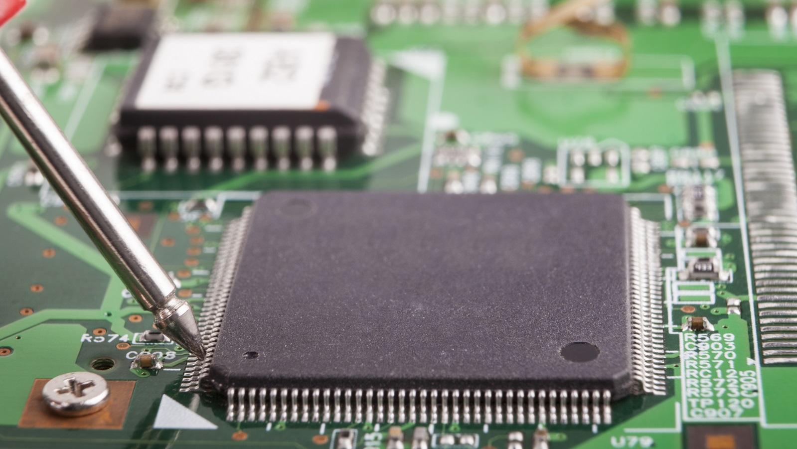
SMD soldering is a process in which the components are mounted onto the surface of the PCB. The components used in this process are known as Surface Mount Devices, or SMDs for short.
Process
Placement: Components are placed on the surface of the board, often done via automated machinery.
Soldering: The common methods are Reflow soldering-Where solder paste will be applied to pads on the PCB, and then the board with components is subjected to controlled heat in a reflow oven, which may cause the solder to melt and form joints.
Advantages
Compact Design: SMD components are normally much smaller compared to their through-hole versions, thus allowing for more compact and high-density PCB designs.
Speed: The process is much more automated, which speeds up building and reduces the cost of labour. Performance: Generally, SMDs are electrically superior owing to short leads, less parasitic capacitance, and less parasitic inductance.
Variety: Normally, surface mount formats provide more variety.
Disadvantages
Repairability: It is very difficult to replace or repair an SMD because they are so small compared to other packages.
Initial Setup Cost: Machinery for SMD assembly is expensive; hence, low volume production is more costly.
Applications
Mobile phones
Computers and laptops
High-density electronic boards
Consumer electronics
DIP Soldering Dual In-line Package
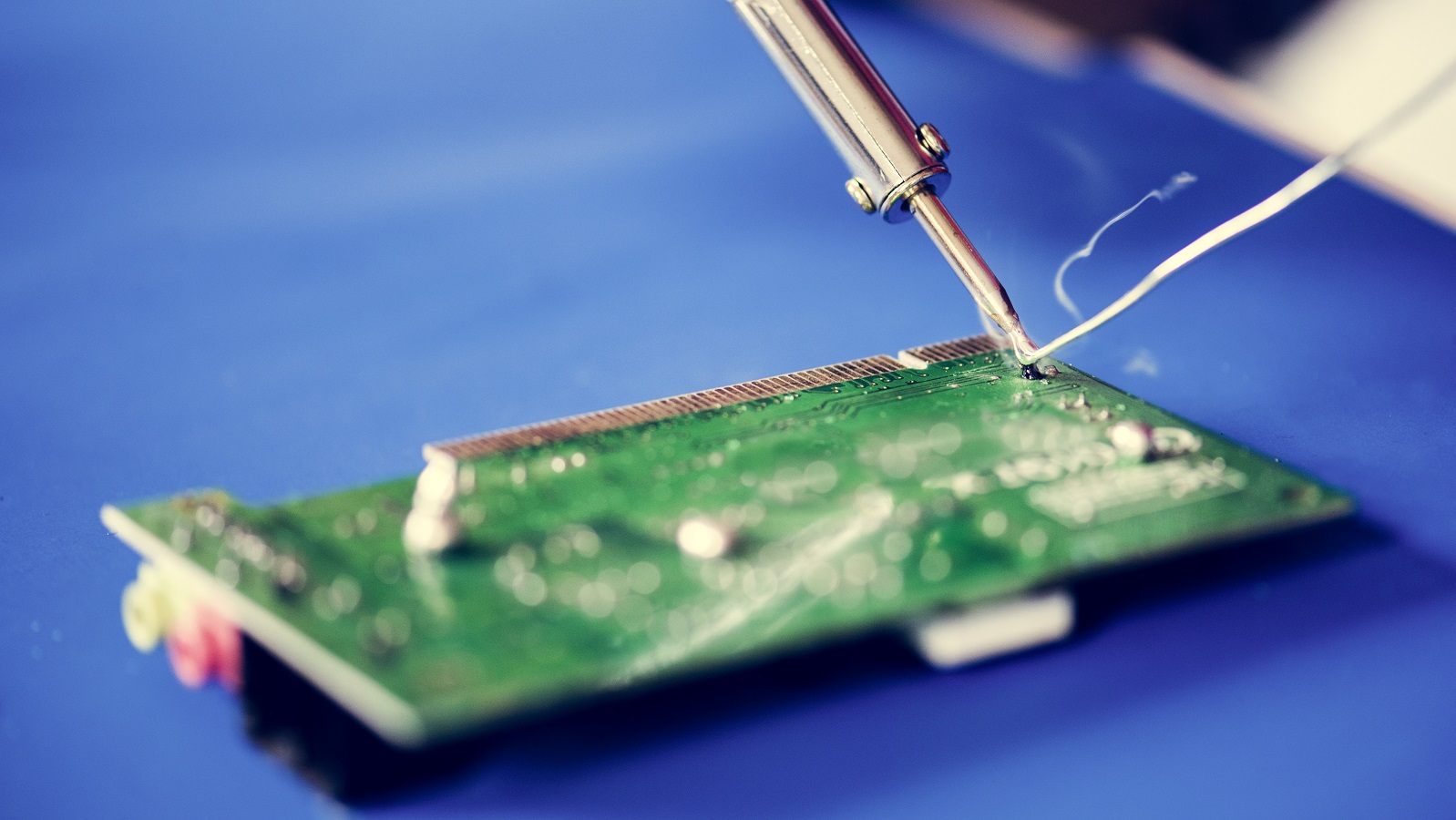
In DIP soldering, the through-hole components have leads inserted into the holes drilled into the PCB and soldered in place.
Process
Insertion: The lead components are inserted either manually or through automated means into the holes within the PCB.
Soldering: It involves wave soldering, where the board with mounted components is passed over a wave of molten solder, and also doing it manually by using an iron.
Advantages
Mechanical Strength: In through-hole components, good mechanical strength is provided, and hence it will prove good in applications that come under high stress.
Simplicity: The process is capable of being done manually, therefore accessibility is easily available without the use of high-priced machinery.
Repairability: Components are easier to replace or modify compared to SMDs.
Disadvantages
Size: Through-hole components are much larger on average, resulting in less compact designs for PCBs.
Speed: The process is slower. A small percentage is completely manually processed and therefore less suited for high-volume production.
Performance: Long leads can lead to higher parasitic capacitance and inductance that will affect high-frequency performance.
Applications
Prototyping and hobbyist projects
Heavy-duty electronics
High-reliability and military applications
Power electronics
Key Differences
Component Mounting
SMD: Components are mounted on the surface of the PCB.
DIP: The components are inserted through the holes to the PCB.
Size and Density
SMD: Allows compact and high-density PCBs.
DIP: In general, it leads to bulkier designs because the components are larger.
Assembly Process
SMD: Highly automated; for example, reflow soldering.
DIP: Wave soldering automates it, but most of it can also be done by hand.
Mechanical Strength
SMD: Less mechanically strong connections.
DIP: Better mechanical strength in its connections.
Repairability
SMD: Its repair or modification is more difficult.
DIP: The component could easily be repaired or replaced.
Cost:
SMD: Higher initial setup cost on machinery.
DIP: Less setup cost and thus appropriate for low-volume production.
Conclusion
The SMD and DIP soldering techniques have their relative advantages and fields of application. SMD soldering is applied in high density, high speed applications, and automated production lines, while DIP soldering is ideal for robustness, easy repair, and lower volume usages. A proper understanding of the various differences between them will help the designers and manufacturers in choosing techniques in view of particular project requirements.
Hot Tags:

Contact us

If you can't find what you're looking for, please contact us.
Article
Printed Circuit Board Assembly (PCBA) employs Through-Hole Technology (THT) and Surface Mount Technology (SMT). THT offers robust mechanical bonds, ideal for high-stress applications, whereas SMT supports efficient, high-density assemblies. Each method has unique advantages and limitations, impacting cost, manufacturing efficiency, and component compatibility. Understanding these differences is key for optimal PCB design.
 2024/09/11
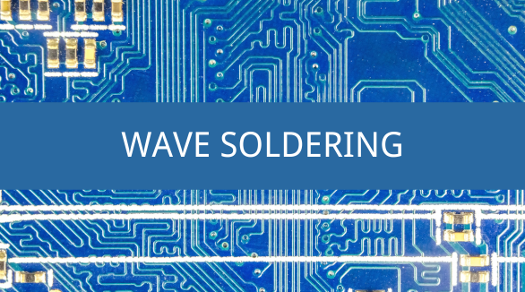
Wave soldering is a PCB assembly process that moves the board over a molten solder wave to create reliable connections. Evolving from dip and drag soldering, it offers consistent, high-quality solder joints. Despite its complexities, it remains essential for through-hole components and complex PCB assemblies.
2024/08/21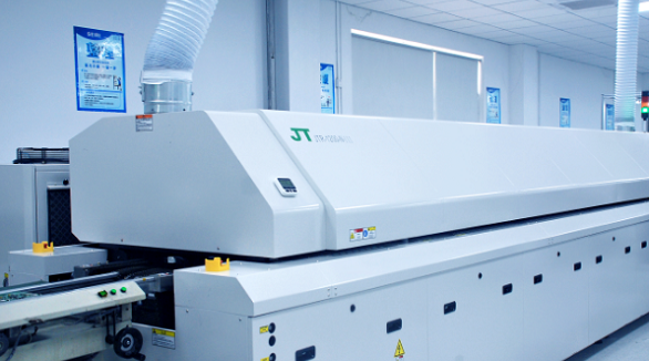
Soldering forms a very important part in the assembly of a PCB. Wave soldering is ideally applied in Through-Hole Technology, while reflow soldering in Surface Mount Technology. Wave soldering involves flux spraying, pre-heating, soldering, and cooling, while in the case of reflow soldering, pre-heating, thermal soak, soldering, and cooling steps are applied. Temperature and time control are the two most critical parameters in the above-mentioned techniques for ensuring soldering reliability.
2024/07/26