Diode Testing
Diodes control current flow in circuits. Regular testing using tools like multimeters ensures performance, reliability, and protection of electronic components.
Diodes are crucial parts in electronic circuits, acting as guardians of current flow. They have been used in different applications ranging from simple rectification tasks to complex voltage regulation. It is thus critical to ensure their proper functioning by accurate testing for the circuit's reliability and protection of other components. This guide explores in detail the techniques and tools used in diode testing, targeting professionals for accuracy and efficiency in work performance.
Diodes play an important role in current flow management and direction, ranging from power supplies down to radio frequency transmissions. The basic construction of a diode is usually a p-n junction made from semiconductor materials such as silicon or germanium. This allows the junction to conduct current in one direction while hindering it in the other-a very essential characteristic that forms the basis for rectification and signal limiting. Based on the previous information provided.

Types of Diodes
Rectifier Diodes are commonly used for converting AC to DC.
Zener Diodes are used for voltage regulation, enabling the flow of current in the reverse direction at a specified breakdown voltage.
Schottky Diodes feature fast switching with a low forward voltage drop, which is extremely useful for very high-frequency applications.
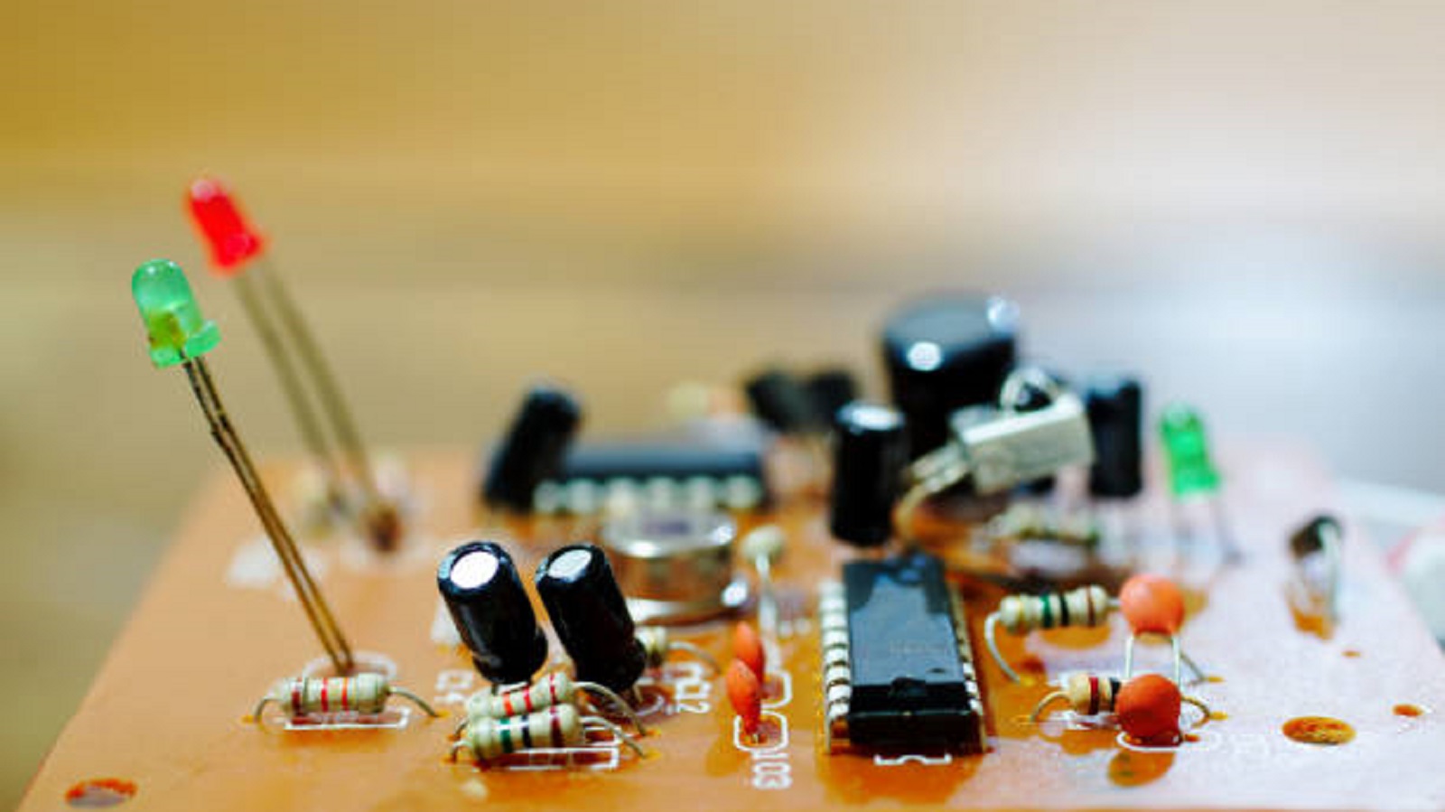
Light-Emitting Diodes find huge application in lighting and indication due to their efficiency in light production.
Tunnel Diodes operate within the negative resistance region and find applications in high-speed circuits.
Photodiodes and Avalanche Diodes have specific functions in light detection and surge protection, respectively.
Knowing the polarity of a diode, especially an anode and cathode, is also essential. Misplacement can mean circuit failure or damage, hence requiring careful placement.
Tools and Equipment Needed for Diode Testing
Diode testing necessitates the following tools and equipment to be carried out effectively:
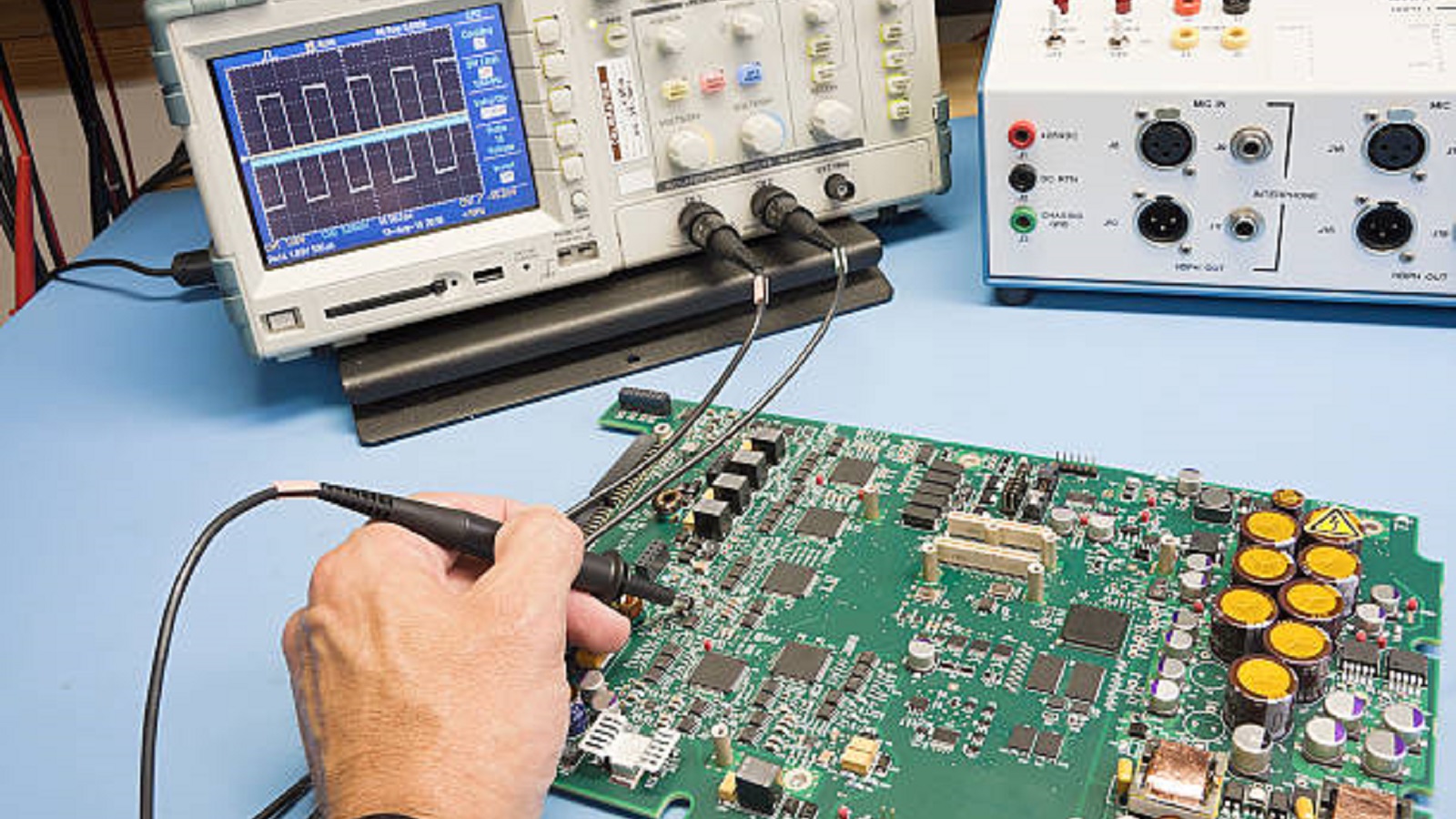
Digital Multimeter: It is the basic tool used to check diodes, and hence, it measures voltage, current, and resistance. Most the modern multimeter has a special mode for diode testing that gives fast and convenient checks of the status of diodes.
Test Leads & Alligator Clips: These provide safety and stability in connections during testing. A good lead minimizes the possibility of faulty or incorrect readings that may further cause damage when testing.
Breadboard: In developing diodes for testing, it makes configurations and connections easier such that multiple configurations are allowed without soldering.
Power Source: An effective power source is needed, mainly in tests such as the zener breakdown where one must apply specific voltages.
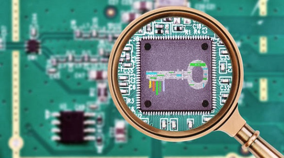
Magnifying Glass or Microscope: Crucial in verifying physical characteristics and damages or defects on the exterior of the diode that may influence performance.
Diode Testing Methods
Continuity and Polarity Check
This is a simple but necessary test to check if the diode is conducted in the proper direction.
Setup: Double-check your meter is set to the continuity setting.
Connections: Connect the black probe to the cathode and the red probe to the anode. Then reverse polarity to check for reverse continuity.
Readings: A beep or low resistance means that the diode conducts properly when forward-biased. When reversed, the multimeter should show high resistance, meaning it blocks current in the wrong direction.
Voltage Drop Test
Assists in verifying that a diode has the appropriate forward voltage drop, important for its operation in a circuit.
Setup: Change the multimeter to voltage reading mode.
Configuration: The red probe is connected to the anode, and the black probe is connected to the cathode.
Observations: In general, silicon diodes have forward voltage drops of 0.6-0.7 volts while germanium diodes are around 0.2-0.3 volts. It should be showing a very high resistance in the reverse direction.
Reverse Voltage Test
This test verifies that the diode properly blocks current when reverse-biased.
Power Source: Provide the reverse voltage by using an appropriate supply.
Observation: The multimeter should indicate high resistance, which will imply that the diode indeed blocks reverse current. A low resistance reading suggests that the diode is short-circuited.
Zener Breakdown Test
Used for zener diodes to determine the breakdown voltage where they allow reverse current.
Setup: Connect the zener diode with a variable power source.
Execution: Gradually increase the voltage until the diode conducts in reverse.
Observation: Measure the voltage at this point to determine the zener's breakdown voltage, which must be equal to the diode's specifications.
Troubleshooting Common Diode Problems
Testing of diodes also includes the troubleshooting of common problems resulting from failure or damage.
Open Diode: This occurs when there is no continuity when forward biased; the diode should be replaced.
Shorted Diode: This occurs when low resistance is present both in forward and reverse biasing, meaning that it is damaged.
Overheating: Due to excessive current or voltage, usually visibly because there is some physical evidence. Make sure the rating for the diode is correct for that circuit.
Using the Wrong Diode Type: Using a type that's not suitable can be quite problematic, often requiring an end-point voltage drop or even poor action. Always use the correct diode for the intended application.

Regular testing of diodes by professionals maintains the performance and reliability of electronic circuits. By verifying whether diodes work correctly, pros can eliminate possible failures in advance, protect other components, and guarantee optimum circuit performance. Proactive testing is part and parcel of standards maintenance in electronics, contributing to the advancement and durability of technology.
Mastering diode testing methodologies greatly improves the efficiency and reliability of electronic assemblies. The understanding of various diode types combined with expert testing practices ensures that your circuit will work the way it should, supporting both technological innovation and operational reliability. This not only helps to preserve the integrity of electronic systems but also serves best practices in terms of circuit optimization and safety.
Hot Tags:
Contact us

If you can't find what you're looking for, please contact us.
Article

PCB test coupons simulate board elements for reliability checks, detecting early issues to ensure quality and performance before mass production.

Solder masks protect PCBs, while paste masks aid precise component placement during assembly, both crucial for PCB reliability and efficiency in electronics.

Flying Probe Testing (FPT) is ideal for low-volume PCB assemblies. It uses mobile probes and advanced features like PDM and HVS for precise, cost-effective detection of shorts and opens.
