- Products & Capabilities

- Simulation Design & EDA

- About
- Resources
Dry Solder Joints


Dry solder joints in PCBs cause unreliable connections, leading to device failure. Prevent with proper heat, cleaning, quality solder, and skilled techniques.
In solder joint integrity in PCB design, performance and reliability of the electronic assemblies are dependent on it. Dry solder joints are among the various challenges, but they are a significant threat to the overall functioning of the device. Dry solder joints are defects that occur when the solder fails to stick to component leads and PCB pads, resulting in poor joints. This text examines the origins of dry solder joins along with methods to identify them and ways to stop their formation along with appropriate methods for their correction to keep PCB assemblies reliable.
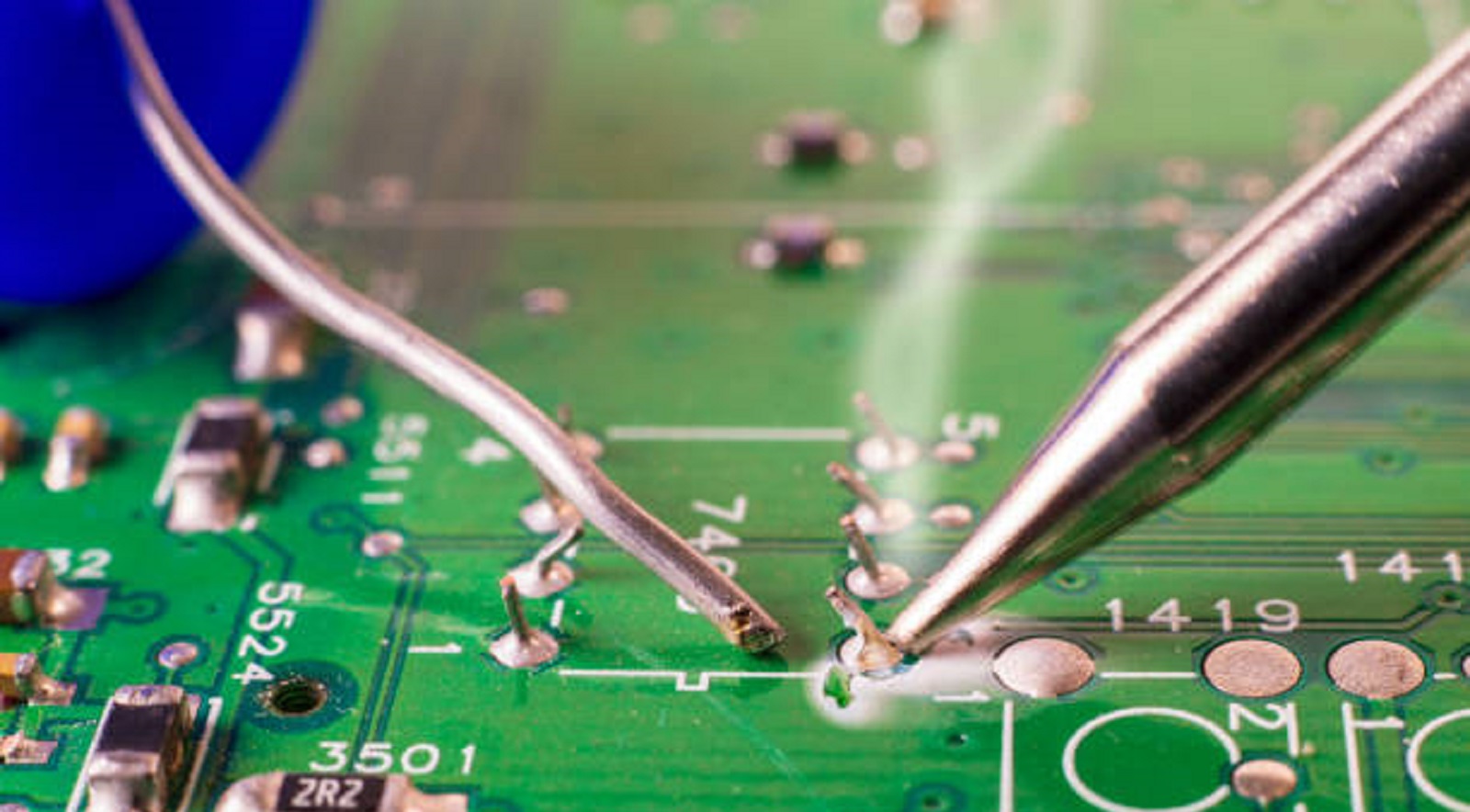
Planting cold solder or dry joints appears after failing to create proper solder connection between component leads and PCB pad intersections. This means untrusty electrical connections and instant device failure or sneakiness during operation. While good solder joints are shiny and smooth, dry solder joints are dull, grainy, and irregular in appearance, showing evidence of failed bonding achieved via soldering.
Causes of Dry Solder Joints
Identification of reasons behind dry solder joints is crucial to rectify and prevent such faults to the best. There are several causes for their formation:
Inadequate Heat
Lack of sufficient heat from the soldering iron or reflow oven may make solder not to melt completely and thereby deny right adhesion on PCB pads as well as on component leads.
Oxidized Surfaces
Regular wetting between leads and PCB pads cannot occur when the contact surfaces present either oxidation or surface contamination. Correct cleaning operations represent a necessary step to allow proper bonding establishment.
Inadequate Soldering Techniques
The soldering process performed manually depends completely on expert professionals to precisely utilize their skills. Dry joint formation occurs because soldering angles and pressing speeds and force application mismatch during the process of soldering.
Inadequate Quality Solder
The poor wetness properties of substandard solder material lead to the formation of numerous dry solder joints across circuit boards.
Fast Cooling
Soldering at rapid rates makes the material set before it can properly bond which creates fragile solder junctures.
Not Enough Flux
The purpose of flux is to wipe away contaminants that prevent surfaces from being ready for soldering. Joints during soldering processes tend to develop deficiencies when flux applications are conducted incorrectly.
Detection of Dry Solder Joints
The quality control of PCB relies heavily on precise identification of dry solder interfaces. A series of procedures exists to detect the defects which include the following steps:
Visual Inspection
Manufacturers can detect dry solder joints with dull and rough or irregular surfaces which do not cover padding or lead ends using magnification tools and automatic optical inspection machines.
Cracks or Fractures
Various substance groups such as liquid crystals and water along with germs are drawn to oxidized or moist surfaces of soldered connections leading to permanent solder joint deterioration. Inspection of categorized defects under both unaided vision and magnified observation is possible.
Inconsistent Performance
Devices operate erratically when dry solder joints appear because they either stop intermittently or shut down completely.
Physical Movement
Dry solder joints between components will move when contacts occur thus demonstrating insufficient mechanical adhesive capability.
Effects of Dry Solder Joints
Dry solder joints produce a collection of critical problems which jeopardize device performance.
Unstable Electrical Contacts
Intermittent operation together with unexpected device failure arises from contacts that flake.
Raised Resistance
When joints become worse wetted they develop increased resistance which leads to higher power dissipation together with local heat production and reduced operational efficiency.
Mechanical Vulnerability
The mechanical forces and temperature changes that identify solder joints cause them to start cracking.
Signal Integrity Issues
Signal degradation and electronic noise emerges because of weak electrical connection during high-speed operating conditions.
Short Circuits
When exposed to air short circuits often develop in dry solder joints causing unintentional connections which damage both components and tracks on the PCB.
Prevention Strategies
To prevent dry solder joints, producers need to follow various essential practices.
Clean Surfaces
Clean any substance or oxide contaminants from component leads and PCB pads with isopropyl alcohol immediately before starting to solder.
Use High-Quality Materials
Strong bonds will result from applying high-quality flux and solder which enhances wetting during the soldering process.
Use Proper Soldering Conditions
Appropriate temperature levels and controlled cooling methods must be used for making successful connections.
Improve Soldering Techniques
The effectiveness of manual soldering increases with practice, while scheduled practice helps prevent dry joints during soldering processes.
Pre-tinning
A strong soldered connection emerges when technicians place thin layers of solder first on the component leads and PCB pads before the final assembly takes place.
Repairing Dry Solder Joints
PCB maintenance calls for an essential maintenance practice that includes dry solder joint repair. The following repair process will lead to successful results:
Wear protective eyewear together with proper ventilation when performing this step. The repair process starts with powering off the device then unplugging it from the mains.
The area surrounding the joint requires cleaning with isopropyl alcohol.
Soldering iron temperature should be maintained at 600-700°F since it is optimal for lead-based solder.
The proper method to eliminate old solder from the joint involves using solder removers along with wick while avoiding too much heat exposure.
The application of a small quantity of optimal flux helps pre-wet the items before performing re-soldering tasks.
Melt both component lead and PCB pad at the same time by using new solder to achieve a shiny clean connection.
Check the fixed joint for a correct finishing appearance and run tests on the equipment to prove successful repair.
Dry solder joints present serious challenges to the integrity and reliability of PCBs, and they result in the degradation of performance and device failure. With effective detection, good prevention methods, and skilled repair procedures, issues can be addressed effectively and high-quality electronic assemblies are ensured.
At PCBX, we are committed to delivering industry-best PCB solutions that prioritize quality and reliability. For expert PCB manufacturing and assembly services, reach out to us. We can together maximize the performance and longevity of your electronic projects. Reach out to us today to receive an online quote and elevate your projects to the next level.
Hot Tags:

Contact us

If you can't find what you're looking for, please contact us.
Article
Reflow soldering is vital for PCB assembly but faces challenges like solder bridging, tombstoning, and voiding. Effective solutions include optimized stencil design, thermal profiling, and precise component placement.
 2024/09/25
SMD soldering mounts small components on the PCB surface for compact, automated designs but has high setup costs and repair challenges. DIP soldering uses through-hole components for robust, easily repairable, lower-volume applications.
2024/09/24
Soldering forms a very important part in the assembly of a PCB. Wave soldering is ideally applied in Through-Hole Technology, while reflow soldering in Surface Mount Technology. Wave soldering involves flux spraying, pre-heating, soldering, and cooling, while in the case of reflow soldering, pre-heating, thermal soak, soldering, and cooling steps are applied. Temperature and time control are the two most critical parameters in the above-mentioned techniques for ensuring soldering reliability.
2024/07/26