High-Frequency PCB
High-frequency PCBs are crucial for fast, reliable tech, enhancing performance in telecoms, aerospace, and more with advanced materials and precise designs.
As time changed and technology in electronics started demanding devices that were much quicker, stronger, and faster, so was the growth of the PCB to keep up with this high pace. Among the technological innovations that have characterized printed circuit boards, the high-frequency PCB stands out as the enabling key for the swift performance required by modern electronic equipment, telecommunications, and space.
A high-frequency PCB is designed to bear high-speed signals from 500 MHz up to several gigahertz. These PCBs form the basis of applications where signal integrity and performance cannot be compromised. Examples include radio frequency communication systems, microwave communication devices, satellite systems, and advanced computer networks.
Core Characteristics of High-Frequency PCBs
The robust functionality of high-frequency PCBs is underpinned by a range of key characteristics:
Low Dielectric Constant (Dk): A very important factor in reducing the delay of signals, improving the transmission of frequency, and avoiding signal distortion.
Low Loss Factor (Df) : The better the performance with fewer transmission losses. The lower the Df, the better the performance will be with fewer losses in transmission.
Coefficient of Thermal Expansion (CTE): The best match to copper foil, which reduces the risk of separation due to temperature variations.
Low Water Absorption: This is critical to avoid Dk and Df variations, particularly in humid environments.
Strong Thermal and Chemical Resistance: High-frequency PCBs must be resistant to environmental stress, withstand impact, and have high peel strength.
Key Materials and Design Considerations
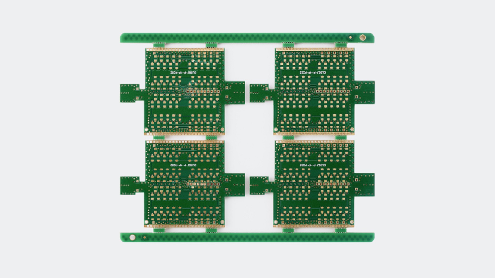
The substrate material selection primarily decides the performance of a high-frequency PCB. Other than FR-4, widely used in conventional PCBs, the materials mainly used in high-frequency PCBs are PTFE, commonly known as Teflon, Rogers, and ceramic-filled hydrocarbon laminates. These materials have low dielectric constants, minimal signal loss, and are also stable over a wide temperature range.
Manufacturing high-frequency PCBs involves paying attention to many design aspects to meet strict requirements set by signals:
Routing Method: Opt for 45-degree bends or curved turns in the PCB layout to minimize high-frequency emission and coupling risks.
Routing Length: Shorter routing lengths help mitigate signal radiation and coupling with adjacent components, essential for high-speed interfaces like DDR, USB, and HDMI.
Number of Vias: Minimize via usage as each introduces distributed capacitance, causing potential impedance discontinuities and signal integrity issues.
Avoiding Crosstalk: This can be avoided by changing the PCB layout to include strategic grounding and spacing to avoid parallel signal traces acting like antennas. Consider adding ground wires or planes, increasing spacing between signal lines, and making orthogonal routing in adjacent layers.
Impedance Matching: Impedance should be matched through the board to avoid reflections that could cause distortion in the signal.
Strategic Decoupling Capacitor Use: Decoupling capacitors near IC power pins suppress high-frequency harmonic interference and ensure power integrity.
Ground Isolation: Isolate analog and digital grounds to avoid interference due to harmonic components, possibly by using choke beads or single-point interconnections.
Minimize Loop Formations: Try to avoid the formation of loops during the routing of high-frequency signals in order to minimize electromagnetic interference potential.
Apply Fly-by Topology for DDR4: The proposed routing topology reduces reflections, thus enhancing signal integrity in high-speed operations.
Apply the 20H Rule: Design the power plane dimensions to be at least 20H smaller on each side than the ground plane to limit RF energy leakage and enhance electromagnetic compatibility.
Applications of High-Frequency PCBs
The applications of high-frequency PCBs vary from use in mobile networks-4G and 5G alike-to many other high-tech industries where the role of high-frequency PCBs proves to be indispensable.
Telecommunications: The main structure in any mobile network, including 4G and 5G, includes high-frequency PCBs, which support high velocities of data transfer required for clear and reliable communication.
Aerospace and Defense: High-frequency PCBs find application in the aerospace industry within radar and communication systems; the need for performance, together with the reliability at extreme environmental conditions, also requires critical testing.
Medical Devices: The use of high-frequency laminates includes but is not limited to imaging systems such as MRI and ultrasounds that rely on high-frequency PCBs.
Automotive Radar Sensors: Enabling complex sensor systems in fully autonomous vehicles, automotive technologies rely on high-frequency PCBs for enhanced safety and better navigation.
Challenges and Future Trends
Developing high-frequency PCBs is not without its own set of challenges. Manufacturing has to be cost-effective while managing requirements for special materials and complicated design procedures. Moreover, with increased frequencies of signals, the propensity of EMI also increases, hence requiring the integration of some form of effective shielding.
The further development of IoT, 5G, and all other next-generation technologies is going to drive innovations into high-frequency PCBs. New material and fabrication techniques are being studied by manufacturing companies to improve the performance by overcoming challenges with heat dissipation and miniaturization.
High-frequency PCBs are not just components, but the backbone of most advanced technological developments. As long as the world is continuing to demand faster and more reliable devices, the role of high-frequency PCBs will be nothing but increasingly important, inspiring innovations that will shape up the future of high-speed communications and other tech-driven businesses. Understanding and adapting the nuances of high-frequency PCB design and manufacturing will be key to companies leading in this dynamic market.
Hot Tags:
Contact us

If you can't find what you're looking for, please contact us.
Article
Raspberry Pi Pico offers affordability and power for DIY projects, while Arduino excels in modularity and community support, catering to diverse project needs.
Select aluminum PCBs for excellent heat management or FR4 PCBs for cost-effective versatility in diverse electronic applications.
PCBs (Printed Circuit Boards) are fundamental in electronics, composed of multiple layers like silkscreen, soldermask, copper, and substrate, chosen for specific electrical functions.