How to Find Fault in PCB Board
PCBs are essential but prone to faults. Diagnosis and repair using tools like multimeters and X-rays prevent costly repairs, ensure reliability, and improve quality.
From smartphones to large industrial machinery, PCBs are the unsung workhorses that underpin modern electronics. Notwithstanding this, faults in PCBs can arise which, besides being tremendously costly to repair, may lead to the loss of device functionality. Identification and repair of these faults are important for ensuring that electronic devices are reliable and last long.This manual covers the most frequent PCB failures, their test methods, and procedures for proper repair and maintenance.
Common Causes of PCB Failures
PCBs have the tendency to fail from a number of reasons, all of which can be easily prevented by some sanity in design and handling:
Solder Bridges: These are formed when the solder accidentally bridges two adjacent pads, causing short circuits. This can be a result of excessive solder or too less thickness of the solder mask layer. Preciseness in soldering and avoiding mistakes in the mask can put off solder bridges.
Acid Traps: Refer to areas on a PCB that have the ability to collect corrosive residues, such as acid flux, which can cause corrosion and eventually electrical shorts. These traps are found in recessed areas of the board or between tightly fitted components. The designer should try to reduce the number of risk areas by allowing more open space and applying protective solder masks.
Plating Voids: These are those voids that occur when there is an incomplete plating of the hole during manufacturing. This results in poor conductivity. Causes include improper plating procedures or incompatible hole size. Following proper plating technique and specifications can avoid plating voids.
Environmental considerations: Most of the variations in PCB reliability depend on humidity and temperature. Components expand and contract, causing fractures, while humidity can cause corrosion. Protective coatings and designs to withstand environmental stress are important for durability.
Aging: With time, PCBs can deteriorate. Components show embrittlement, the connections loosen, and corrosion may set in-all these lead to performance problems. Using corrosion-resistant finishes and designing for durability are crucial to extending the life of a PCB.
Electromagnetic Compatibility (EMC) Issues: Poor design leading to electromagnetic interference (EMI) can affect performance. These can be resolved through optimized grounding and design adjustments to minimize interference.
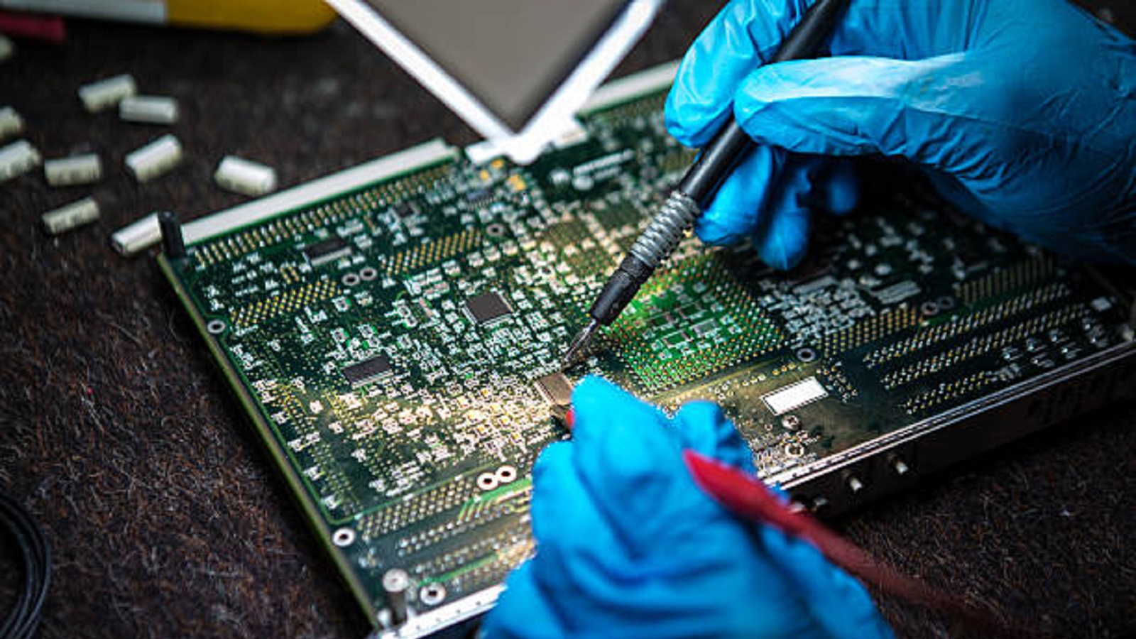
Types of PCB Faults
Soldering Faults: Known as "dry joints," these arise from inadequate solder connections, leading to intermittent or unreliable electrical contact. They can be due to incorrect solder temperatures or misalignment during component placement.
Temperature Faults: Extreme temperature fluctuations can cause components to expand or contract rapidly, leading to physical stress and failure. It is important to take into consideration in the design phase operational and storage temperatures.
Non-Wetting Faults: Poor adhesion of solder to the surfaces of a PCB due to inferior finishes or long storage conditions affects quality. This fault often relates to insufficient solderability or plated thickness.
Methods of PCB Fault Detection
Visual Inspection: Utilize magnifying equipment to check the evident look for any damage to the PCB, like cracks or incomplete soldering. This is usually one of the initial steps toward diagnosis because surface-level defects can be visibly identified rather fast.
Multimeter Testing: Perform resistance and continuity tests in order to find out open circuits or shorts. It is important to have this in order to verify the integrity of electrical connections within the board.
X-Ray Inspection: X-rays can detect internal defects such as internal cracks or unsoldered joints hidden from the naked eye. This is necessary for detecting faults within layers when there are multi-layer boards.
In-Circuit Testing: This is done by means of special test equipment, which measures the functioning PCB for deviations that occur during its operation. It provides information concerning the electrical performance and pin-points failures. Infrared cameras detect hotspots-a region of excessive heat that may indicate component stress or failure. This is vital in locating those components prone to premature failure.
Repairing Faulty PCBs
When faults are detected, a structured approach to repair becomes necessary:
Damaged Components Removal: Desolder and remove defective components with care. This will avoid further damages on the board and give way to a correct component replacement.
Cleaning of Solder Pads and Tracks: Use the soldering iron or desoldering pump to eliminate excess solder and debris. Cleaning provides better adhesion and electrical connectivity.
Apply Copper Tape: Lay copper tape over damaged tracks in order to create electrical connections between these. This approach will renew the flow of conductivity on the PCB and thus keep it working.
Resolder Joints: Effectively solder new or existing components in place using the right amount of heat to avoid damage to the board or any other surrounding components.
Repair Through-Holes: Clean and, if needed, resize through-holes, reinserting components afterward. Proper repair allows for maintaining structural integrity.
Replace Components: Position new parts in place and solder them carefully, taking care to position them correctly so as not to compromise function.
Remove Excess Tape: After any repairs, excess copper tape should be carefully removed to maintain a clean and operational board surface.
Benefits of Debugging PCB Faults
Cost Savings: Early detection and correction of faults prevent expensive rework or replacement costs.
Improved Product Quality: Ensures the reliability and performance of the end product, thus enhances customer satisfaction and brand reputation.
Enhanced Efficiency: Correcting design and manufacturing process flaws improves production efficiency and reduces time to market. This increases the reliability of the device over time and prolongs its life cycle.
Design Intelligence: Debugging finds those valuable, much-needed insights for future optimizations and improvements in design.
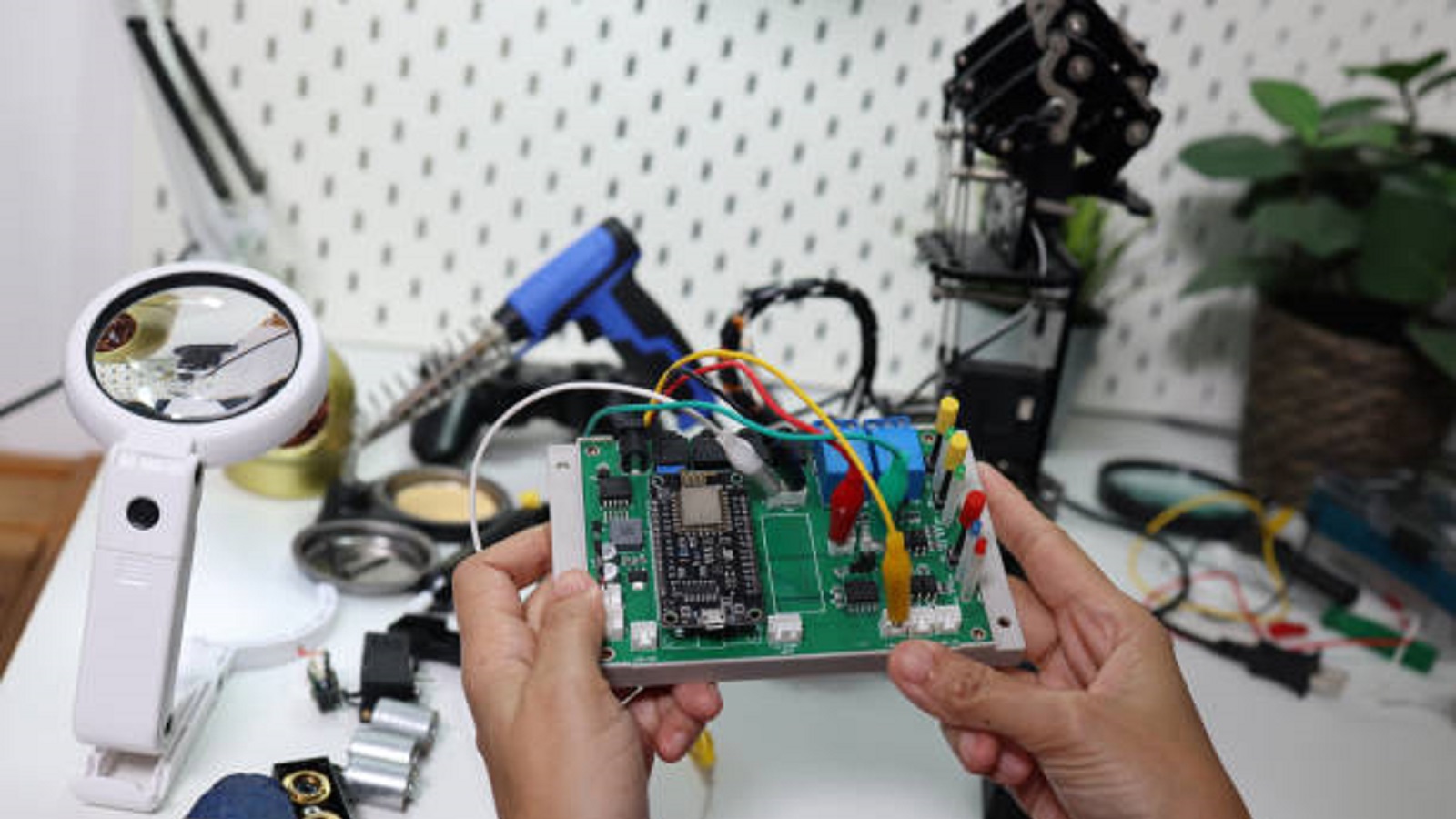
PCBs are complex and prone to different types of faults. These would range from manufacturing defects all the way to environmental effects. The above-mentioned challenges are very effectively reined in through systematic identification and repair techniques, using the right tools-such as multimeters, x-rays, and thermal imaging. Reliability and performance, throughout its operating life, can be maintained by PCBs with the use of stringent inspection and test conditions, in addition to stringent design and manufacturing practices. In this respect, fault finding and repair become a structured process necessary to keep the standards high in today's electronic manufacturing.
Hot Tags:
Contact us

If you can't find what you're looking for, please contact us.
Article
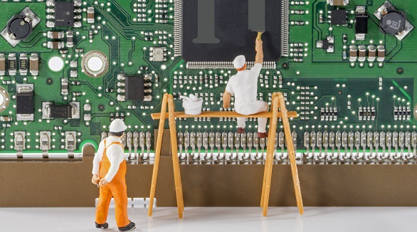
PCB repair skills reduce waste and costs, ensuring durable electronic functionality by effectively diagnosing and fixing various board failures.

PCB recycling is vital to reduce environmental hazards and recover valuable materials, especially copper. Effective methods include mechanical, chemical, and thermal processes, significantly benefiting sustainability.
Printed Circuit Boards (PCBs) are crucial yet prone to corrosion, leading to malfunctions or failures. This article outlines detecting corrosion signs, preparing for cleaning, required materials, and step-by-step cleaning methods using isopropyl alcohol or alternatives. It also covers drying, reassembly, and preventive measures. Seek professional help if corrosion is severe.
