- Products & Capabilities

- Simulation Design & EDA

- About
- Resources
How to Mount Power Supply to PCB


Mounting power supplies on PCBs optimizes space, reliability, and performance. Key factors include layout, thermal management, and mounting methods.
The mounting of a power supply on the PCB falls under the indispensable point in the world of electronics design and has an impact on the overall functionality and durability of the whole system. Power supplies enable the delivery of the necessary voltages and currents to electric circuits. Such an integral part allows suitable power supply selection and their proper mounting in the process of a PCB design so that it functions reliably and serves efficiently.
Types of Power Supplies and Mounting Techniques
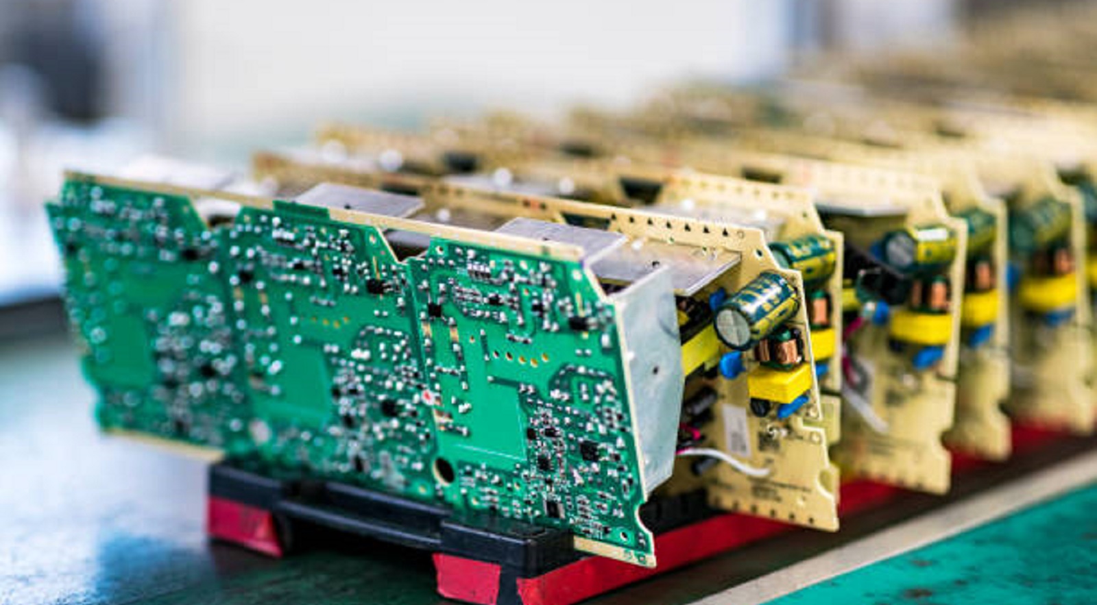
Power supplies are available in several formats-preliminary to being mounted directly onto a PCB-such as AC-DC wall adapters, DC-DC converter modules, and open frame power supplies. When choosing the power supply and mounting method, the parameters that need to be considered include: available board area, supply footprint and pinout, required mechanical robustness, heat dissipation capability, and type of specific PCB assembly process to be used.
Common Mounting Schemes
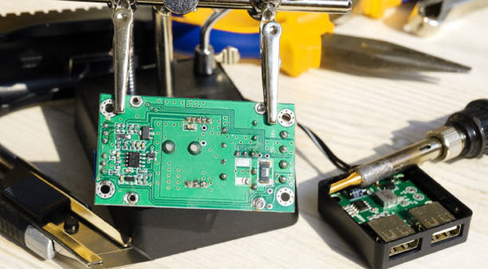
Through-Hole Pin Mount: In this mounting scheme, the pins are inserted through plated through-holes within the PCB and then soldered in place. It offers excellent mechanical coupling. Quite good for high-vibration environments, although requiring extra space, along with a wave solder process.
Surface Mount Pad Mounting: This is the reflow soldering method for power supplies with particular surface mount footprints. It reduces footprint and makes trace routing easier; however, it might require careful solder joint control due to possible susceptibility to vibration and reduced heat transfer efficiency.
Screw/Standoff Mounting: Power supplies are screwed onto the PCB with standoffs for strong mechanical retention and good service access. On the other hand, this method adds assembly steps and requires board space for hardware.
Panel Mounting: It is useful where board space is at a premium; a power supply is mounted on a panel and wired to the PCB.
DIN Rail and Adhesive Mounting: DIN rail mounting is done industrially, but lightweight supplies can also make use of adhesives on uneven surfaces; generally, however, these are less robust.
Key Selection Considerations
When selecting a power supply for PCB mounting, it's vital to consider:
Board Area: Make sure the footprint of the power supply fits the available space and doesn't interfere with adjacent components.
Mounting Requirements: The supply's mounting holes, pinout, and connectors should be matched to the PCB's capability and assembly process.
Heat Dissipation: Determine if the thermal output of the power supply can be adequately handled by the area on the PCB.
Structural Strength and Reliability: Assess the weight and center of gravity of the power supply and whether the PCB will support it without flexing.
EMI/EMC and Safety Standards: Ensure the power supply provides assurance of meeting relevant standards for noise emissions and susceptibility protection.
PCB Layout Considerations
To do a PCB layout capable of housing the power supply effectively, consider the following key aspects:
Area and Layers: Ensure enough board space for the power supply and enough layers to route out the power pins without significant crossovers.
Pin Mapping and Pads: Associate board layers with the power supply's pin functions; use large pad sizes for stability.
Thermal Management: Add thermal pads connected to inner ground layers to aid in heat sinking.
Routing and Noise Coupling: Design trace widths to carry load currents and avoid noise coupling into sensitive circuits.
Safety Considerations: Adhere to spacing rules between hazardous potentials for device safety.
Techniques of Mounting
Thru-Hole Pin Mounting
This joining method of mechanical robustness consists of sticking long pins into the PCB and soldering them. These assure very firm anchoring, but it occupies more board space and requires wave soldering assembly.
Recommendations:
Co-ordinate spacing of pins to match plated hole pattern spacing
Apply relevant annular ring pad
Provide solder wave clearance
Attach thermal pad to the ground plane
SMD Pad Mounting
Surface mount techniques have a compact footprint, and with reflow soldering, placing the power supply is straightforward.
Recommendations:
Size pads to match design of power supply
Locating pads leaving space for solder masking
Thermally attaching pads to internal layers
Liberal fillet and thermal reliefs
Screw/Standoff Mounting
Screw assembly offers great Mechanical stability, at the cost of higher assembly works.
Guidelines:
Locate standoff footprints at supply corners
Allow adequate room around the supply for access
Employ oversized pads and provide for assembly clearances
Thermal Management Strategies
Efficient thermal management plays an important role in the avoidance of overheating of a power supply:
Via PCB: Thermally connect thermal pad to the GND plane. Provide adequate area of copper to take heat away.
External Sinks and Conduction: If possible, sink plates; mount using thermal gap pads
Convection: Keep adequate air circulation and attach forced air as required.
Layout Considerations: Use copper fill around the supply as much as possible while modeling its heat dissipation capabilities.
Best Practices for Integration
For effective integration of power supplies on PCBs:
Power supplies should be selected early to drive the layout process.
Establish early in the process the mechanical spacing and interface requirements.
Prototype board assemblies that will serve to confirm component fit.
Check vibration and shock resistance ratings.
Test the electrical performance under conditions of operation.
Inspect solder quality and connections thoroughly.
Mounting power supplies directly on a PCB can save so much space and, sometimes, big money compared to external modules, improving the general reliability and integration of the device. Careful selection of the appropriate type of power supply, its mounting method, thermal considerations, and layout principles will definitely ensure a robust and efficient functional power delivery system within an electronic device. With great planning and the use of best practices, the design of a PCB can easily make this crucial part of the product a key contributor to its performance and success.
Hot Tags:

Contact us

If you can't find what you're looking for, please contact us.
Article
Preheating PCBs enhances soldering by reducing thermal shock, improving wetting, and activating flux, using methods like conduction, convection, and IR.
 2025/01/24
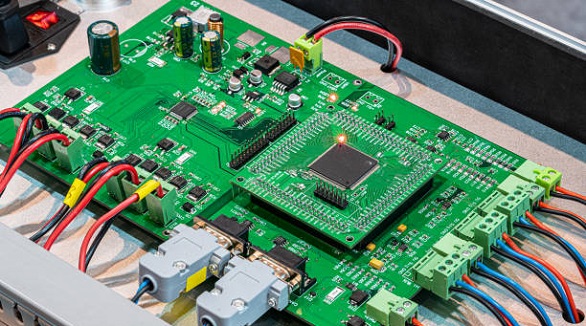
Electronic module assembly is crucial for innovation, driven by demands for high-performance, reliable modules in fields like connectivity and electric transportation.
2024/12/31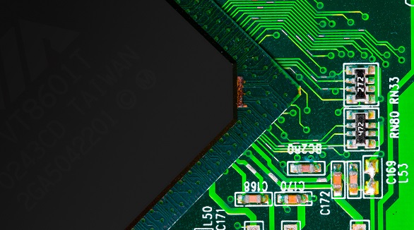
Tab routing enhances PCB production efficiency and quality, ideal for complex shapes. It offers cost-effectiveness, flexibility, and protection, crucial for high-precision designs and panelization.
2024/10/23