How to Prevent Short Circuits
PCB short circuits arise from unintended connections, leading to safety risks. Prevention involves isolation, inspections, and thermal protection, ensuring device reliability and safety.
Printed Circuit Boards form the basis of most electronic circuitry used today. Despite their resounding importance, short circuits in PCBs are one of the most frequent problems that compromise functionality and safety in most electronics. A short circuit on the Printed Circuit Boards occurs when unwanted electrical connections between conductors result in an excessive flow of current and hence present some hazards. This tutorial deals with the nature of PCB short circuits by identifying signs and causes of PCB short circuits, and it also explains precautionary measures to minimize risks.
Understanding PCB Short Circuits
A short circuit in a PCB is an unintended and usually damaging connection between conductive traces or components on a circuit board. In a good design, there would be distinct traces, electrically isolated, to help proper functionality of devices. However, some of the many causes of unintentional bridging of traces can be in manufacturing flaws, design oversights, external reagents, or physical trauma. These allow current to veer from its intended flow path because of surges that cause overheating, damage, or possible fire hazards.
Signs of PCB Short Circuits
Recognizing early signs of short circuits can allow diagnostics in due time, to avoid the probable escalations. These include:
Burn Marks or Discoloration: The localized overheating caused by a short circuit may leave burn marks or discoloration on the surface of the PCB.
Burning Smell: A characteristic, frequently sharp smell, with hints of plastic burning, is another common hint toward a short circuit condition, indicating overheated components.
Erratic Operation: Devices exhibiting unintended shutdowns, erratic responses, or intermittent operations could be a sign of a short circuit hidden from immediate view.
It is important that these symptoms are scanned in due time; otherwise, acting late can result in severe device failure or safety hazards.
Causes of PCB Short Circuits
This wide-ranging understanding of the causes can help in devising effective prevention strategies:
External Contamination: PCBs contaminated by dust, moisture, or residues-particularly conductive materials such as metal fragments or flux-are especially prone to the formation of unintended conductive paths.
Internal Conductive Anodic Filament (CAF) Growth: Electrochemical reactions in the internal layers of a PCB can, with time, give rise to the development of conductive filaments that bridge traces and cause short circuits.
Solder Paste Issues: Incorrect or misplaced solder paste application at manufacture can cause solder bridges on components which result in electrical shorts.
Design Errors: The most common design issues are related to incorrect or insufficient spacing and/or incorrect netlists. These can make a PCB susceptible to an unintended connection or short.
How to Diagnose Short Circuits on PCBs
In order to diagnose a short circuit on a PCB, one has to adopt a very structured approach:
Visual Inspection: Perform the visual inspection of the PCB with good lighting and magnifying equipment. The first thing to look for is a sign of physical trauma: burn marks, discoloration, or physically damaged components.
Thermal Imaging: Utilize infrared cameras to trace thermal anomalies. Hotspots emanating as an area of unusual warmth typically indicate excessive current flow associated with a fault condition, usually a short circuit.
X-Ray Inspection: In multilayer PCBs, X-ray technology allows internal inspections without their physical dismantling, hence hidden faults or bridging.
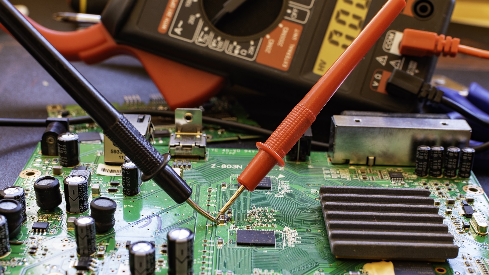
Destructive Testing: When non-destructive methods are inadequate, one may need to dismantle the PCB for direct exposure to components. Conduct multimeter tests on the exposed pads to electrically isolate the problematic areas.
Prevention of PCB Short Circuits
Minimizing the chances of PCB short circuits is a proactive affair; here are the significant precautionary measures:
Isolation Techniques: Use isolation slots or trenches on the PCB to physically separate high-voltage and low-voltage traces, dampening the risk of shorts from voltage differentials.
Design Rule Checking (DRC): Make use of DRC software, which enforces compliance with design rules and thus will not allow any spacing and clearance violations that may inadvertently cause connections.
AOI-Automated Optical Inspection: Employ AOI systems during and after the assembly phases of the board. These systems use state-of-the-art imaging to check for soldering defects, which particularly have a tendency to create solder bridges, leading to short circuits.
Controllable Current Limiting: Introduce limiting components such as resistors in series with critical traces. This will limit the flow of current and, therefore, protect other components in case any fault occurs.
Thermal Overload Protection: Install thermal protection devices, cutoffs, or fuses that disengage the circuit in case of excessive temperature rise and prevent overheating that could lead to a short circuit.
Conclusion
The best way to deal with short circuits in PCBs is to ensure the operation of electronic devices is reliable, safe, and long-lasting. By understanding the causes and signs of short circuits and putting in place effective prevention, both the manufacturers of PCBs and their end-users can reduce these electrical accidents significantly. With good design considerations, regular maintenance, and application of traditional and advanced diagnostic techniques, it would be possible to protect electronic equipment from the harmful effects of PCB short circuits, hence ensuring better performance of devices and safety for their users.
Hot Tags:
Contact us

If you can't find what you're looking for, please contact us.
Article
PCB recycling is vital to reduce environmental hazards and recover valuable materials, especially copper. Effective methods include mechanical, chemical, and thermal processes, significantly benefiting sustainability.
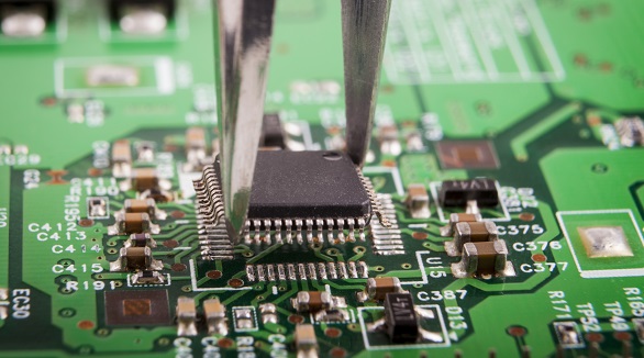
Still, SMT can further feature defects such as solder bridging, cold solder joints, tombstoning, and solder balling. Grasping the very common faults and their solutions is the key toward effective PCB assembly and reducing SMT errors—very much in line with the trend toward PCB miniaturization and higher component density.
Thermal management is all about more than just keeping the temperature of electronic systems and printed circuit boards low. It has been a key issue related to reliability and performance. Of the very basic fundamentals that would be studied in the field, some are concerned with methods of heat transfer. These are through conduction, convection, and radiation. The methods of cooling include natural cooling, forced-air cooling, fluid cooling, and evaporation cooling. Appropriate thermal design rules shall be followed wherein the chosen materials provide optimum thermal conductivity and the components of a system are so laid out that no hot-spotting will take place. Thermal analysis becomes critical in pointing out heat-related issues and optimizing the design. It thus minimizes failure rates and enhances stability and functionality of the electronic systems through comprehensive thermal management.
