How to Solder Chip Components
Master soldering chip components on PCBs using proper tools and techniques, ensuring precision and reliability for both hobbyists and professionals in electronics.
Soldering chip components such as resistors, capacitors, and integrated circuits onto printed circuit boards is a pivotal skill in electronics. Whether for hobbyists or seasoned professionals, creating precise and reliable solder joints is fundamental to the functionality and durability of electronic devices. This guide offers a detailed approach to soldering chip components, covering all aspects from essential tools to soldering techniques, common pitfalls, and quality assurance, ensuring professional and high-quality results.
Basic Soldering Tools
The correct tool should be selected to ensure a successful chip component soldering process with efficiency and precision, which minimizes any possibility of damage to sensitive parts.
Soldering Iron
The soldering iron forms the heart of your tool kit. When choosing one, take note of the following characteristics:
Tip Size: Fine conical or chisel types, 0.5mm to 1.5mm, provide the desired precision for the small-sized components.
Temperature Control: This is crucial for adjusting heat based on the size and thermal mass of the components. In most cases, a temperature range of 650°F to 700°F is suitable.
Power Rating: A power rating of 15W to 65W offers versatility in terms of handling various soldering jobs.
Ergonomics: A lightweight and comfortable handle is vital for long hours of use without fatigue.

Solder Wire
The choice of solder wire plays a critical role in soldering:
Composition: 60/40 or 63/37 tin/lead rosin core solder is the most reliable for most applications; they have good melting points and flow characteristics.
Diameter: Thin diameter, 0.5mm to 1.0mm, allows for precision application and control of solder quantity.
Additional Tools
Tweezers: Fine tip tweezers facilitate precise placing and adjusting of small components on the PCB.
Diagonal Cutters: Flush cutters are necessary for properly trimming through-hole component leads.
Magnifying Glass/microscope: Such gadgets, like magnifying glasses and microscopes, come in helpful during the quality inspection of solder joints.
Vacuum Pickup Tool: This serves for the manipulation and positioning of minute SMDs.
Solder Station
A well-arranged solder station enhances the productivity and safety of the work:
Iron Stand: Serves for safely resting the iron during its standstill period.
Tip Cleaning: Make use of brass wool and parabolic cleaners for cleaning iron tips for effectiveness.
Board Stand: The stand holds the PCB at a comfortable angle so that both hands can be free to do the soldering job.
Soldering Techniques
Good soldering techniques are necessary to make strong and functional solder joints.
Preparing Components
Clean and Tin: Clean all the component leads and PCB pads from oxidization using isopropyl alcohol. Pre-tinning them with solder will ensure better adhesion and flow.
Preparing Soldering Iron
Clean the Tip: Before use, always clean the soldering iron tip with a damp sponge or brass wire to remove any oxidation and then tin it with solder for good heat transfer.
Soldering Process
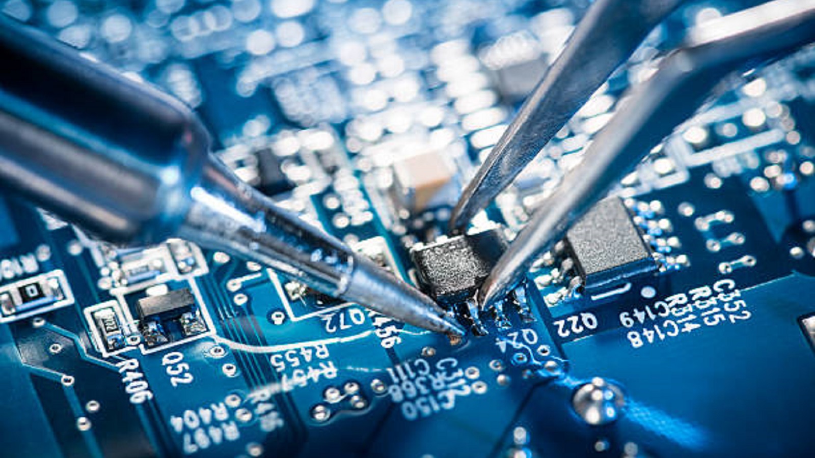
Position Components: Place components on the PCB using either anti-static tweezers or a vacuum pick-up tool. Position the correct orientation and alignment of parts per circuit design.
Correct Heat Application: The soldering iron tip is applied between both the pad and component lead simultaneously to elevate the two to soldering temperature; this method ensures there is no cold joints by correctly preheating the interface.
Solder Application: Apply solder to the joint from the other side of the iron. The heat will pull the solder into the joint, making a solid connection. Remove the iron and let the joint cool, without disturbance, to avoid imperfections.
Inspect Each Joint: After cooling, look at solder joints under magnification to make sure the connection is smooth and well-formed, with no defects in the joint, such as bridging or cold joints.
Through-Hole Components
Bend and Insert Leads: Lightly bend leads on through-hole components to help them stay in place for soldering. Insert through the PCB, making sure they are seated properly and aligned.
Solder and Trim: Solder leads on either side for good connections, then cuts excess length of lead with flush cutters.
SMD Components
Tack and Align: Apply a small amount of solder to tack down one side of the SMD component into place. Adjust as necessary to make sure it is correctly aligned.
Minimize Solder Use: Apply minimum solder when attaching each pad to avoid bridging, ensuring a clean joint.
Avoiding Common Mistakes
Not Enough Heat: Do not underheat the joints for any reason, as that leads to weak cold solder joints.
Excess Solder: Only use enough solder to form the joint, avoiding blobs or bridges which create electrical shorts.
Overheating: Quickly and efficiently apply heat to prevent damage to components or lifting pads from the PCB.
Flux Residue: Clean any residual flux with isopropyl alcohol to prevent corrosion and electrical leakage over time.
Post-Assembly Inspection
Comprehensive Visual Inspection: After assembly, inspect each solder joint under magnification, ensuring smooth, complete coverage without defects.
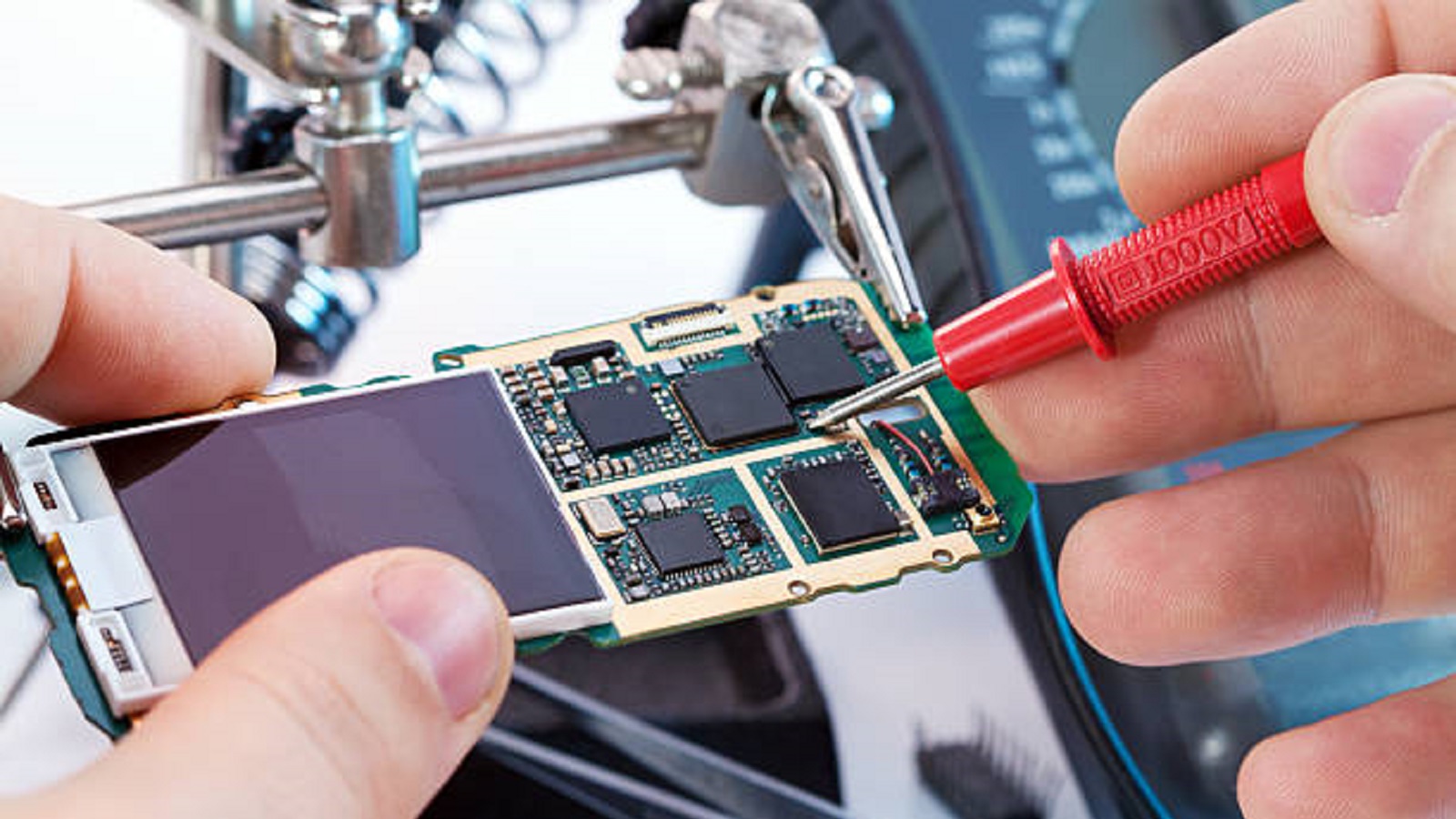
Functional Testing: Verify that the built circuit works as per the schematic drawing for operational integrity.

Soldering chip components requires a little patience, some precision, and the right tools. With thorough preparation of workspace and components, proper techniques in soldering, and careful joint examination, perfection in soldering for high quality and reliability can be achieved.
Practicing these methods will empower you to confidently assemble and repair PCBs, whether for personal projects or professional work in the field of electronics. Through dedication and attention to detail, you can transform soldering into a skill that not only serves your creative and technical needs but also sets the foundation for future innovations in the electronics domain.
Hot Tags:
Contact us

If you can't find what you're looking for, please contact us.
Article

Solder masks protect PCBs, while paste masks aid precise component placement during assembly, both crucial for PCB reliability and efficiency in electronics.

Solder masks protect PCBs from damage and solder bridging. Available in various types and colors, they ensure reliability. Eco-friendly options and precise thickness measurements are crucial for quality.

Ball Grid Array (BGA) components, such as PBGA, CBGA, CCGA, TBGA, and CSP, provide high I/O density, improved reliability, and high-quality electrical and thermal performance. Quality assembly and functionality are assured since advanced soldering and inspection methods are required, like AXI and AOI. Proper storage and handling shall guarantee the performance of the devices.
