- Products & Capabilities

- About
- Resources
How to Test a PCB Board with a Multimeter


A multimeter is vital for electronics, measuring voltage, current, and resistance. This article covers its basic functions, settings, and guides you on PCB testing, ensuring accurate and safe troubleshooting.
The multimeter is one of the most versatile and useful tools for any electronics hobbyist or technician. A multimeter may be used to test components and track down problems at the circuit board level since it can measure voltage, current, and resistance. In any case, whether it's for designing a new project, troubleshooting a device that has gone faulty, or simply learning more about electronics, being able to test circuits with a multimeter is a critical skill. This article will help you grasp the basic functions and settings of a typical multimeter and show you how to test a circuit board using one.
What is a Multimeter?
A multimeter is useful test equipment for troubleshooting and measuring electrical circuits. It is a handheld device that is used to measure a variety of electrical parameters of a system, including:
Voltage: This is used to measure AC or DC voltage.
Current: used to measure amperage in AC and DC circuits.
Resistance: this is measured in ohms; it is how well a material opposes the flow of current.
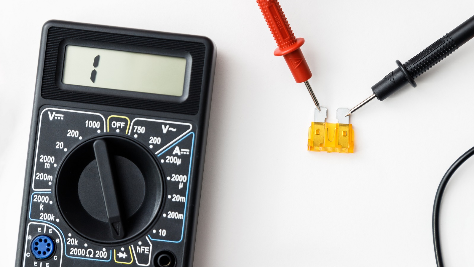
Many multimeters have other measurement modes, such as diode tests, capacitance measurement, frequency counter, duty cycle, and temperature measurement. Digital multimeters display readings through an LCD, while analog versions have a needle meter. Almost all have the metal-tipped probes safely inserted into the circuits to be tested for voltage, current, and resistance.
Preparation Steps
Before testing any circuit board, here are some preparatory steps to ensure the attainment of accurate and safe readings:
Safety First: Power the circuit board off before commencing work.
Visual Inspection: Examine obvious damage—broken traces, cracked solder joints, scorched components.
Note Potential Problems: Mark any suspicious areas that would require closer scrutiny.
Step-by-Step Guide to Testing a PCB with a Multimeter
Choosing the Correct Measurement Function
Select the correct measurement function on the multi-meter for your test. The typical settings for voltage and resistance tests are 20V DC or 200kOhm. Always remember to set the meter to the appropriate AC or DC setting.
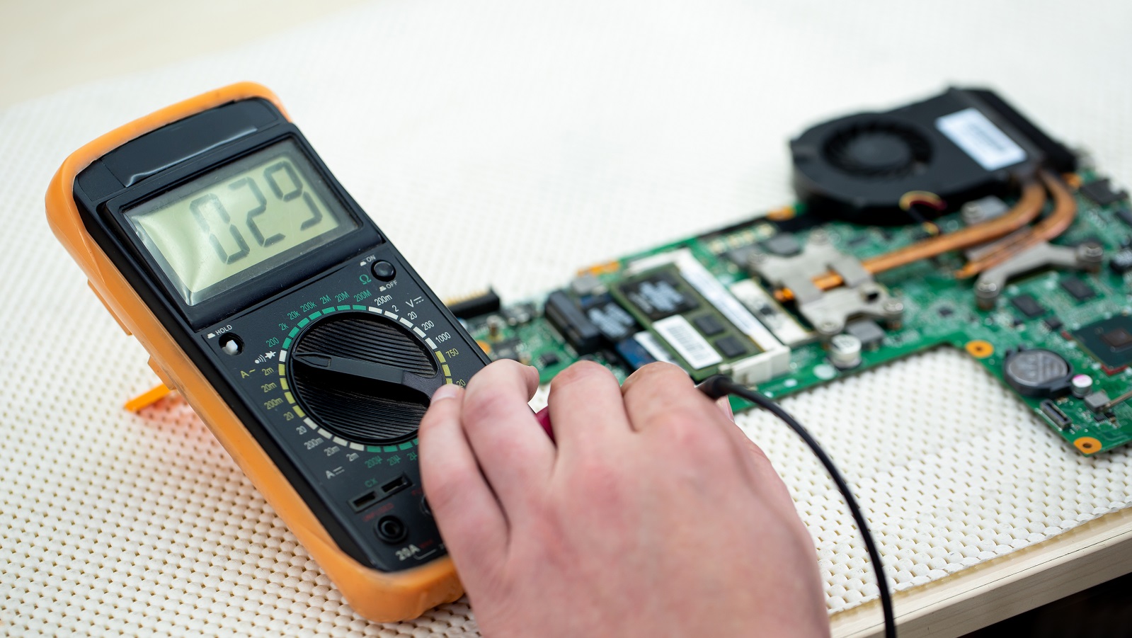
Checking Voltages
Testing voltage is basic troubleshooting. Here's how to do it:
Set the Multimeter: To the DC voltage setting when testing a DC circuit.
Connect Probes: The black probe goes to common ground, and then you use the red probe to probe test points between components.
Measure: Voltage readings at many test points should be compared against a schematic. Large discrepancies could mean there is a fault with connections or a power delivery problem.
Resistance Measurement
Measurements of resistances could test for continuity and resistor values:
Set the Multimeter: On the setting for resistance measurement.
Measure Resistances: Probes at either end of resistors to measure their values to compare with labeled or specified values per the schematic diagram.
Check for Shorts or Opens: Probe across sections of the circuit to check for negligible or expected levels of resistance.
Testing Components
Different components, like transistors, capacitors, and inductors have to be individually tested as follows:
Transistors: Infinite in one direction, very low to none in the other.
Capacitors: Very low capacitance reading, which can indicate that the capacitor has been drained or is faulty.
Diodes: The diode test function can measure the voltage drop in a forward-biased state.
Identifying Problems
Finally, summarize your findings by taking note of those areas where:
Voltages: deviate considerably from the expected values.
Resistances: indicate shorts or opens.
Component: values are way out of tolerance or the component has faulted.
Continue sweeping up and down the signal chain to further isolate issues
Advanced Measurement Techniques
Static Measurement
This involves powering off the circuit and looking for telltale signs of damage or faults in every discrete component, including:
Short Circuits: Check for any shorts between the power supply and the ground.
Diodes and Capacitors: Test if they are working well.
Intermediate Components: Check that they are within specification.
Online Measurement
Taken when the circuit is running or powered:
Overheating Components: Check and replace them if necessary.
Logic Gates: Test for proper logic operation of digital circuits.
Crystal Oscillators: Ensure the output is normal.
Conclusion
Testing a PCB board using a multimeter involves several systematic checks that assist in making sure all components and pathways are working properly. Be it the preparation and proper function selection, voltage, resistance, or individual component checks, every step is taken with the purpose of diagnosis and troubleshooting. How a multimeter measures various parameters, coupled with an orderly work procedure, enables technicians and hobbyists to maintain and repair circuit boards for the reliable performance of electronic devices.
With these guidelines, you're on your way to confidently test and troubleshoot your PCB boards using your multimeter as a powerful tool.
Hot Tags:

Contact us

If you can't find what you're looking for, please contact us.
Article
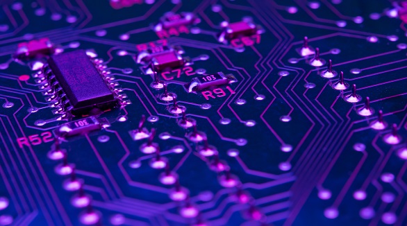
PCBs (Printed Circuit Boards) are crucial in electronics, providing mechanical support and electrical connections via etched copper traces on a non-conductive substrate. They ensure signal integrity, heat dissipation, and contribute to compact, reliable, cost-effective designs preferred in electronics manufacturing.
 2024/08/28
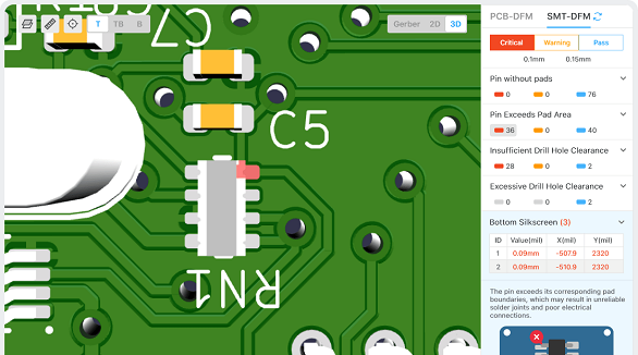
The article is developed concerning the breakthrough of integrated circuits and the need for custom PCBs in some electronic products. It enumerates ten golden rules in conducting PCB layout design and manufacturing: grid selection, routing, power layers, component placement, panel duplication, component value combination, frequent DRC, flexible silkscreen use, decoupling capacitors, and pre-production parameter checks. These rules provide for the optimum design and manufacturing of a PCB.
2024/07/25
Most electronic circuits are mounted on PCBs, or Printed Circuit Boards, which provide mechanical support and electrical interconnection of electronic components. There are, however, special applications that involve the use of single and double-sided PCBs, multi-layer PCBs, or even rigid and flexible PCBs with aluminum backing, targeting medical, industrial, auto, and aerospace industries. They may use materials such as fiberglass, epoxy, aluminum, and others.
2024/07/25