Lead vs. Lead-Free Solder
Lead-free solder, safer for the environment, requires higher temps and careful handling; lead solder offers ease but poses health and environmental risks.
Solder is an important part in the electronics industry, and it enables the making of strong electrical connections on PCBs. With increasing interest in the environment and evolving technology, the debate of lead-based versus lead-free solder comes into play. This article has identified the differences between the types of solders-advantages and drawbacks-both lead-based and lead-free-and how they impinge on today's manufacture of electronics.
Solder is a fusible metal alloy used to join metal surfaces and provide a strong and conductive bond that is essential in making the device functional. History has positioned lead-based solder as the standard because of its favorable characteristics; however, increasing regulatory, health, and environmental concerns have propelled the shift toward lead-free alternatives.
Lead Solder
The lead-based solder is usually a tin-lead alloy, often in the ratio of 60/40 or 63/37. A number of reasons probably explain why lead-based solder has been favored:
Low Melting Point: The melting point of lead solder is about 183°C (361°F). This relatively low melting point reduces thermal stress during manufacturing, thus minimizing damage to sensitive components and substrates.
Excellent Wetting Properties: It flows easily and wets well on metallic surfaces, thus providing strong, reliable joints with a bright, smooth appearance.
Usability: Lead solder is easy to work with and comparatively cheap, hence it finds its application in many areas.
However, lead is a potent neurotoxin, and exposure to this metal creates serious health hazards. It easily penetrates the body by inhalation, ingestion, or through skin, creating serious risks for workers and requiring special cautious treatment. These risks have made the regulation of lead content in electronic devices quite aggressive in recent years.
Lead-Free Solder
Due to health and environmental concerns, severe regulations have been imposed on the use of lead. The European Union's Restriction of Hazardous Substances (RoHS) directive and similar programs worldwide require a reduction in lead usage in electronics. Thus, forcing the electronic industry to switch to lead-free solder alternatives since 2006.
Lead-free solder is typically an alloy of tin with other metals, such as silver, copper, bismuth, or zinc. The combinations seek to match the performance characteristics of lead-based solder yet remain within the regulatory norms. Typical examples include the SAC series of alloys: tin-silver-copper.
Higher Melting Point: Lead-free solders melt in the range between 217°C and 227°C (423°F - 441°F), and thus require process and equipment changes to handle the higher temperature and energy use.
Environmental and Health Safety: Without lead, these solders are much safer for both manufacturing environments and the end-users, thus being in line with global sustainability initiatives.
Varied Composition: With different combinations of metals, solder properties can be engineered to meet particular performance needs, thus allowing flexibility in design.
Key Differences
Melting Point
Lead Solder: Consistent and low (183°C), thus enabling easier temperature control during production.
Lead-Free Solder: Higher and variable, which may affect sensitive components and for which recalibration of soldering profiles may be necessary.
Wettability
Lead Solder: Better wetting characteristics, hence giving reliable and defect-free joints.
Lead-Free Solder: Lower wettability, which could result in non-uniformity in the joints unless carefully controlled.
Physical Characteristics
Lead Solder: Easily results in shining, smooth joints
Lead-Free Solder: Tends to give a dull finish, requiring more skill in application for the same appearance.
Advantages and Disadvantages
Lead Solder
Advantages:
Better wetting and handiness
Less chance of thermal damage due to the lower temperature of melting
Sufficiently cheap for mass production.
Disadvantages:
Severe health hazards involved in dealing with lead
Legislative restrictions to its application within most markets
Toxics lead to pollution of the environment.
Lead-Free Solder
Advantages:
Meets environmental and safety standards set globally
Eliminates poisoning from lead during processes and applications
More promising application in high-corrosion operational environments
Disadvantages:
Requires more temperature, which affects power consumption and heat-sensitive parts of components.
Generally, it is more difficult to work with because of lower wettability
Often more expensive because of the inclusion of precious metals such as silver
Transition to Lead-Free Solder
The transition to lead-free processes should be a strategic move towards the prevention of loss in product quality and reliability. These include:
Equipment and Process Adjustments: Reflow ovens and soldering stations may require recalibration to handle higher temperatures; energy consumption will be affected and equipment wear may increase.
Material Evaluation: Selecting components and substrates that can endure higher thermal cycles without damage is essential for maintaining board integrity.
Training and Quality Control: More effective training of personnel in proper handling and application techniques, combined with stringent quality controls, is required to ensure consistent and reliable joint formation.
The decision on whether to use lead or lead-free solder represents a trade-off among performance, regulatory compliance, environmental responsibility, and manufacturing cost. While lead-based solder provides ease of use, coupled with reliable joint formation, environmental and health implications require the use of lead-free options in so many applications. Other than the electronics industry, new solder formulation and manufacturing technique research will be required in order to bridge the remaining performance gaps and enhance the adaptability of lead-free solders. This evolution has ensured that electronics manufacturers can meet strict standards of safety and environmental requirements without sacrificing product excellence or market relevance.
Hot Tags:
Contact us

If you can't find what you're looking for, please contact us.
Article
SMD soldering mounts small components on the PCB surface for compact, automated designs but has high setup costs and repair challenges. DIP soldering uses through-hole components for robust, easily repairable, lower-volume applications.
The article provides a step-by-step guide to soldering a PCB, covering workspace setup, essential tools, and safety measures. It explains heating the soldering iron, applying flux, tinning the iron tip, placing components, heating joints, applying solder, cooling, inspecting, and cleaning. Emphasis is on practice and safety for successful soldering.
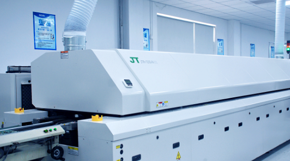
Soldering forms a very important part in the assembly of a PCB. Wave soldering is ideally applied in Through-Hole Technology, while reflow soldering in Surface Mount Technology. Wave soldering involves flux spraying, pre-heating, soldering, and cooling, while in the case of reflow soldering, pre-heating, thermal soak, soldering, and cooling steps are applied. Temperature and time control are the two most critical parameters in the above-mentioned techniques for ensuring soldering reliability.
