- Products & Capabilities

- About
- Resources
Mastering PCB Drill Sizes


Understanding and correctly specifying PCB drill sizes ensure board functionality and manufacturability. Drill sizes affect electrical connections, stability, and signal integrity in PCB design and assembly.
The success of a PCB design project is achieved by understanding its drill sizes to warrant a solid and functional board. At PCBX, we understand the technicalities of the drill sizes in PCB and are always bound to heed your calls with precision and effective solutions as far as your design needs are concerned. Here's an in-depth look at how to guide you through standard PCB drill sizes and how to navigate custom requirements.
Significance of Drill Sizes in PCBs
Drill sizes in PCBs determine the size and diameter of holes that may be required for specific applications, mounting of components, or forming through-hole vias for electrical interconnection between layers. The proper specification of drill sizes optimizes electrical and mechanical features along with aspects related to assembly. A wrongly specified drill size could introduce major production problems.
Types of Holes in a PCB
Plated Through Holes (PTH):
Integral for the insertion of thru-hole components and to provide electrical paths between layers. These are plated with a conductive material.
Non-Plated Through Holes (NPTH):
Mainly used for mounting hardware. These do not offer any kind of electrical interconnection since they are not plated.
Blind Vias:
Outer layers are connected to one or more inner layers without going through the whole board.
Buried Vias:
These connect internal layers only without the appearance of the outside layers.
Standard PCB Drill Sizes
Standard PCBs could use a number of drill sizes to suit a wide range of components and uses. Here are typical dimensions:
Via Holes: Normally in the range of 0.15 mm up to 0.35 mm
Component Lead Holes: Normally from 0.4 mm to 1.2 mm.
Mounting Holes: Mounting holes are typically in the range of 2.0 mm to 3.0 mm, based on the mechanical fastener to be employed.
Drill Size Specifications
This means the ideal size of a drill should be 0.3 mm bigger than the size of a component lead. For instance, when a component has a lead of 0.5 mm, then it is recommended to use an 0.8 mm hole. Get the minutest of details about your project and match the specifications of components with the right drill sizes for proper and reliable connections along with stability in structures.
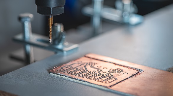
Advanced Custom Solutions
While standard drill sizes are often applied in many cases, special requirements frequently require special drill sizes that can be precisely achieved only by sophisticated CNC machines. Here at PCBX, we welcome such special requests with the ability to fabricate drill holes to exact project specifications, which enable us to maintain functionality and integrity.
Factors Affecting Drill Size Selection
Component Specifications
Quality Hole size must match component lead diameters to provide proper fits and good solder joints.
Manufacturing Capabilities
Pre-check the capabilities and tolerances of your PCB manufacturer to set expectations against what is achievable.
Signal Integrity
Which becomes crucial in high-frequency designs where via and hole size can affect signal quality and integrity.
Mechanical Strength
Sizing adequately for mechanical fasteners will assure board stability without the compromise of structural integrity.
Drill Size Calculation
To perform a calculation of the correct drill size for any PCB project, consider:
Identify the Lead Diameter
Always take the thickest lead of that component for finding the required size of the hole.
Minimum Hole Size Calculation
In such calculation, one may use this formula:
Minimum Hole Size = 0.25 mm + Maximum Lead Diameter.
Pad Diameter Calculation
The best pad can be designed with the following formula:
Pad Diameter = (Minimum Annular Ring × 2) + Minimum Hole Size + Minimum Fabrication Allowance.
Check the Component Density Levels
Level A, B, and C help determine the complexity and appropriateness of the footprint geometries and can help determine the overall design strategy.
Best Practice for PCB Drill Sizes
Use Standard Sizes: Using standard sizes can expedite production and reduce costs.
Check Manufacturer Capability: Verifying a manufacturer is capable will ensure that specified tolerances are achieved.
Utilize Design Software: Prepare drill tables using schematic or design software of PCBs, exporting them into the necessary format which may be Excellon.
Conclusion
Accurately specifying drill sizes is very important in the design of Printed Circuit Boards, as it directly affects the functionality and quality of the board. At PCBX, we merge expertise with the most advanced tooling to offer standard or custom drill sizes according to your project needs. Whether standard or customized, our solution ensures precision, robust functionality, and reliability to make your design process seamless and efficient.
Since the correct drill sizes for a particular job can make all the difference, a little insight and correct application can go a long way in ensuring your circuit boards are optimized for performance, durability, and manufacturability. Reach out to the professional team at PCBX for expert guidance on how we can help you to meet your specific drill size requirements in discussing your next PCB project.
Hot Tags:

Contact us

If you can't find what you're looking for, please contact us.
Article
Etching is crucial in PCB production, removing unwanted copper to create conductive pathways. Techniques include chemical, laser, plasma, and photochemical etching, each with advantages and limitations ensuring PCB performance and reliability.
 2024/09/24
Design for manufacturability (DFM) in PCB production ensures quality, reliability, and cost-effectiveness by optimizing component selection, placement, trace routing, materials, and testing, leading to reduced costs, better products, and faster market entry.
2024/09/24
Backdrill in PCBs removes stubs in vias to improve signal integrity and impedance control, crucial for high-frequency, multilayer boards. It’s vital in communication, servers, medical, and aerospace applications.
2024/08/01