PCB Edge Mount
PCB edge mounting optimizes space, enhances modularity, and improves connectivity by placing connectors on board edges, aiding in flexible, efficient system design.
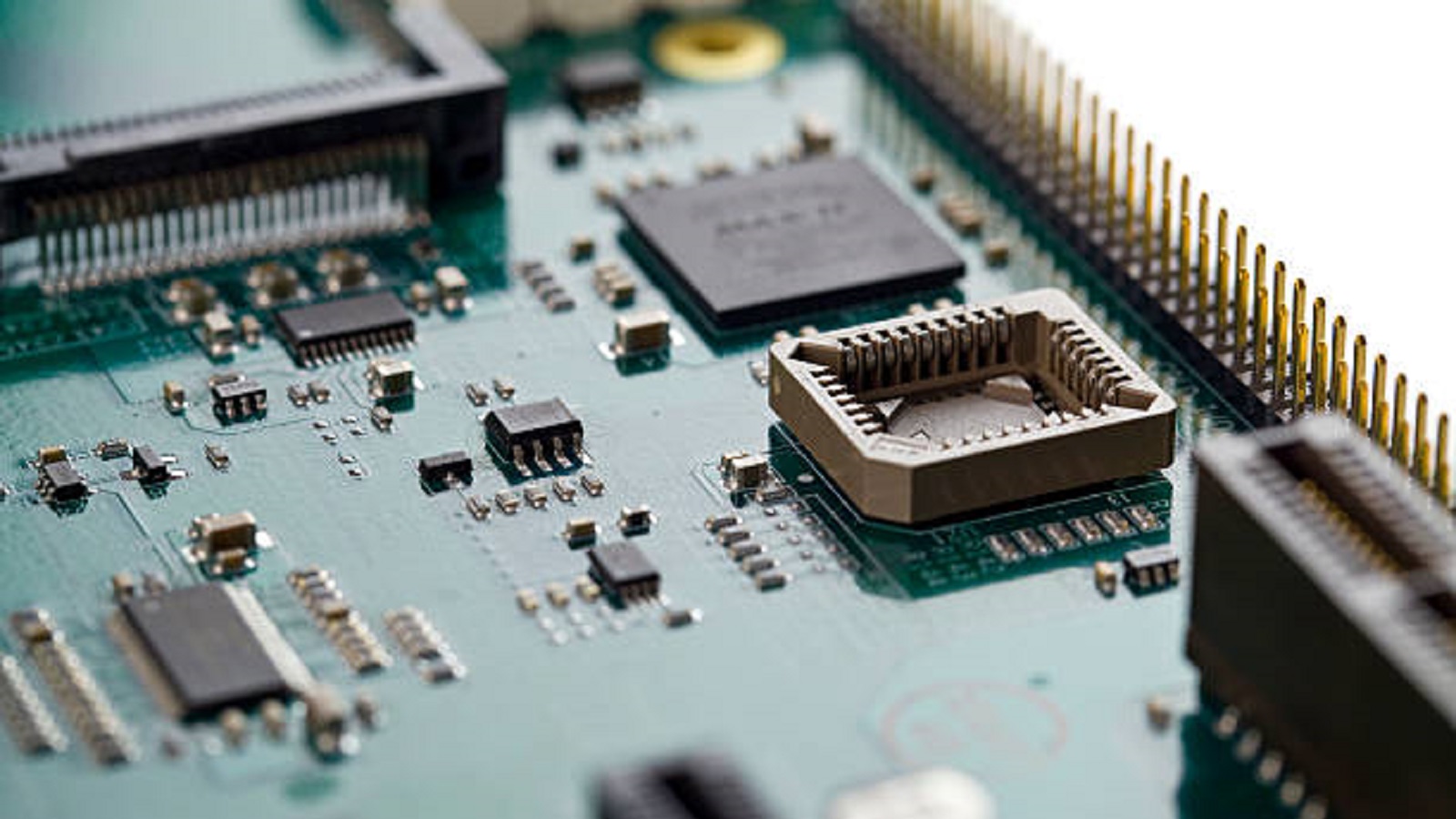
The key concern for the engineers in modern electronics engineering is how efficiently the printed circuit board (PCB) will be used. One method for optimizing space and connectivity which is gaining traction lately involves PCB edge mounting. The approach plays a crucial role in enhancing modularity and functionality of electronic systems, allowing components, and specifically connectors, to interface along edges of a PCB.
In PCB edge mounting, connector modules are installed on the edges of a circuit board rather than soldering cables directly onto the board. This provides for external electronics to be connected more easily and saves valuable surface space on the PCB itself. This is very useful in big systems where space and flexibility become critical.
Common Applications
Due to its adaptability, the edge mount connector finds many areas of application:
Pluggable Daughtercards: Used in large systems to add additional functionality.
Digital Processor and Memory Card Add-ons: Facilitate easy upgrades and expandability in computing devices.
Control Equipment Sensor Wiring Interfaces: These can have sensors connected with ease regarding an industrial control system
Analog Data Acquisition Card Cabling: This allows inclusion of analog signals into systems of data acquisition
Benefits of Using Edge Mount Connectors
Using edge mount connectors instead of soldering edges provides quite a few advantages:
Removability: Easy card swapping and upgrade paths without disturbing the whole setup.
Pitch Options: High-density mounts maximize contact in confined PCB zones that allow greater design flexibility.
Strain Relief: Increased resistance to vibration and frequent cycles of mating.
Simplification in Testing: Providing a testing and prototyping capability, which does not affect the core system
Custom Configuration: Designs tailored according to a particular application requirement, supporting module-based expansions.
Saving Time: Quicker to install compared to manual wiring, resulting in quicker maintenance.
Types of PCB Edge Mount Connectors
The industry offers different types of edge mount connectors to meet various demands, such as the following:
Board-to-Wire Edge Mounts: These connect PCBs to external device cables, usually with high current and voltage ratings, and are very well-suited for industrial controllers and power supplies.
Board-to-Board Edge Connectors: These serve to connect daughtercards or peripheral modules within systems. Most often, they have gold-plated contacts handling signals and power for applications like telecom and computing.
Wire-to-Board Single Row Headers: These have double beam female contacts with optional board locks and friction lock strain relief. Suitable for analog signals and measurement systems.
Key Considerations for Edge Connectors
When planning to use edge mounts on your PCB, consider the following:
Pitch and Contact Density: Align with signal count and available board edge.
Current Loads: Ensure the connector supports the necessary power requirements.
Mechanical Stresses: Account for potential stresses from vibration and temperature shifts.
Signal Types: Opt for gold-plated contacts when handling low-level logic signals.
User Access Needs: Ensure designs facilitate easy probe access for testing.
Assembly Methods: Match the connector type with the available soldering or press-fit technologies.
Compliance Needs: Ensure adherence to relevant safety and EMI/EMC standards like IPC, UL, and CSA.
Cost Targets: Analyze options for budget and performance trade-offs
By considering these factors intelligently, engineers can come up with an edge connector that can meet the performance, reliability, and cost efficiency of their application.
How to Edge Mount a PCB
Edge mount is implemented in a planned systematic manner:
Finalize on Edge Zone: The space available for edge connectors should first be determined at the board design stage. Spacing or clearance requirements should be considered during the laying out.
Select an Edge Mount Product: By pitch, density, current capacity, and compliance. Test samples if necessary to help determine the quality.
Design Housing Cutout: Footprint dimensions - footprint should be matched up with the mechanical drawing and tolerances accounted for within the CAD.
Assign Reference Designators: Document location of contact pads in preparation for assembly; add parts into Bill of Materials.
Prototype PCB Fabrication: Build a few test boards to fit and function check before full production.
Electrical Testing: Continuity and signal integrity between board pads and connectors are checked.
Conduct Reliability Testing: Subject assemblies to environmental and mechanical stresses to ensure resiliency.
Finalize Documentation: Update datasheets, design documents, and manuals with detailed edge mount specifications.
Proper execution of every stage is very important to confirm the quality and reliability of the final product before shipping.
Practical Applications
A number of real-world use cases present benefits associated with PCB edge mounting:
Memory Module Edge Connectors: Facilitate easy upgradeability of personal computers through insertion into motherboard sockets with dense contacts for data and power.
PLC Analog Signal Cards: Add programmable logic controller input/output functionality with plug-in edge mount cards, which simplify field wiring for quick changes.
Inverter Drive Controller Cards: Use edge connectors to interface control electronics with high-voltage modules in motor drives, and make allowances for PWM signals in harsh industrial environments.
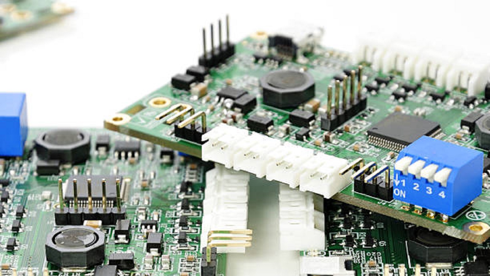
PCB edge mounting gives designers a powerful tool to modularize and expand functionally electronic systems. Thus, enabling efficient use of board space, promoting flexibility with removable and configurable connections for next-generation product development in terms of capabilities and reliability, the concept supports engineers by enabling them to take advantages of the benefits of edge mounting while creating sophisticated, adaptable solutions for an increasingly connected world.
Hot Tags:
Contact us

If you can't find what you're looking for, please contact us.
Article
Burn-in boards are vital for testing semiconductor reliability, simulating stress to reveal defects, ensuring high-quality devices before mass production.
Cold solder joints result from improper soldering, impacting PCB performance. Detection and prevention via proper technique and equipment ensure reliability.
Routine inspections and proper maintenance of capacitors and resistors in PCBs reduce failures, prolong device lifespan, and lower maintenance costs.
