- Products & Capabilities

- Simulation Design & EDA

- About
- Resources
PCB Flying Probe Test


Flying Probe Testing (FPT) is ideal for low-volume PCB assemblies. It uses mobile probes and advanced features like PDM and HVS for precise, cost-effective detection of shorts and opens.
Testability is one of the primary aspects of designing PCBs for the assurance of fabrication of error-free, fault-less circuit boards by way of various techniques and methods.
Flying Probe Testers: An Overview of the What, Why, and How
Traditionally, in-circuit testers championed the testing of PCB assemblies. It was latterly taken to a new high by the flying probe testers in the testing exercise.
In-Circuit Testing (ICT)
In-circuit testing, also called "white box testing," is the functionality testing of a PCB assembly. The technique uses electrical probes to test for the absence of shorts and opens and to measure resistance, capacitance, and other basic properties. Traditionally, ICT has relied on a "bed of nails" fixture, where there is a custom-made fixture with spring-loaded pogo pins contacting designated test points on the PCB assembly (PCBA). Each pogo pin correlates to a node or test point on the PCBA.
These custom ICT fixtures, however, can be very expensive, especially when dealing with complex assemblies. The turnaround time to create these fixtures takes days, so ICT is not suitable for smaller production runs or prototypes because of the cost and time inefficiencies of this test method.
Introduction to Flying Probe Testing
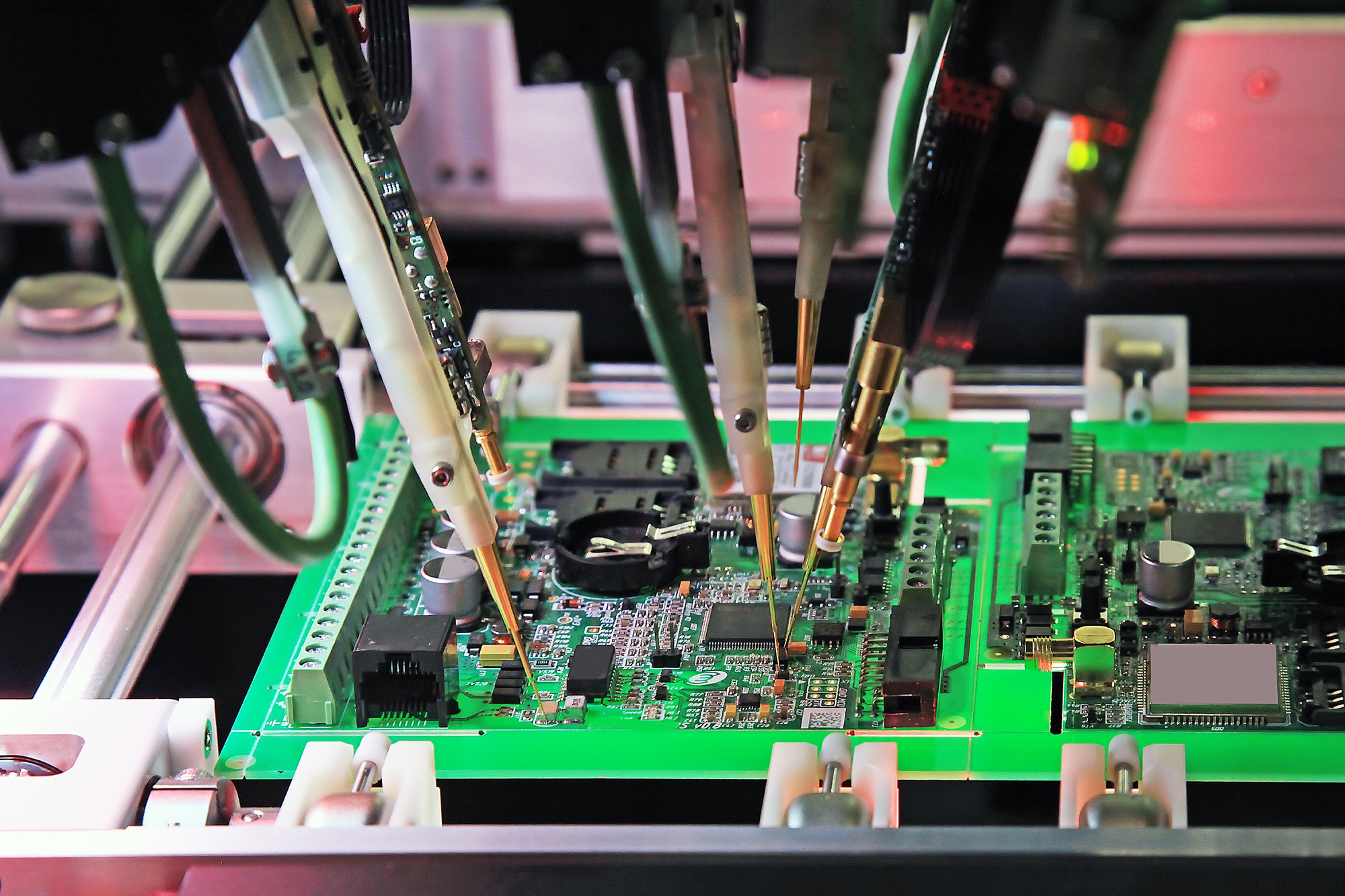
The term flying probe test (FPT) describes a test process whereby mobile test probes move from one test point to the next, following a trajectory programmed by software specifically created for the board under test.
Modern flying probe testers are fitted with cameras to verify the polarity of components. This, coupled with the trend toward miniaturization in electronics, continues to make the FPTs very popular. If board real estate is small in electronic devices, so are test points. As such, FPT has now become the preferred method for low-volume and prototype circuit-board testing since it is easier to program and better suited for complex and densely populated boards.
Improvements in FPT technology continue to raise test coverage, ensuring quality and time reduction in testing. Thus, there is great potential for FPTs in reducing product design cycles and accelerating time-to-market.
How Flying Probe Testing Works
We will now discuss the flow or process of flying probe testing and list the main steps in this test method.
How to Create a Flying Probe Test Program
To test a circuit board assembly using FPT, first, the test program needs to be generated with an FPT test program. Ordinarily, this program would be created offline on a PC, just like the development of an SMT program for a pick-and-place machine. The overview of the creation process is as follows:
Generating Test Program:
Any FPT system would come with a Test Program Generating Application on a PC.
This application requires the BOM of the PCB assembly and the ECAD file. Gerber files are not enough, an intelligent CAD file like ODB++ format, IPC-2581 format, or in native format from some ECAD software tools like Allegro, Altium, PADS, etc used for the design of the PCB.
- The BOM should be provided in Excel format.
- The generated test program is then loaded into the FPT tester.
Testing Process
Loading of the Assembly:
- A board or array of PCB assemblies to be tested is placed on a conveyor belt.
- This conveyor belt transports the assembly into the tester area where the probes are located.
Running the Test Program:
- As the test program is executed, the probes move according to the instructions contained in the program.
- The probes make contact with the pads and unmasked vias at the points called out by the test program.
- The FPT system applies electrical test signals and power to those probe points and makes the measurements.
Measurement and Analysis:
Using signal generators, DC and AC power supply, sensors, a multiplexing system, digital multimeters, and frequency counters—all as determined by the test plan—the tester's hardware activates the PCB nodes. By separating component segments between testing probes from the other interconnections, it is possible to measure component values precisely even when the component is integrated into the circuit.
Defect Detection:
- The FPT system, in its effort to detect faults, checks for shorts, opens and measures the values of components correctly.
- The polarity of components is checked by the integrated cameras; in addition, they can also perform "diode" impedance tests at the inputs of the integrated devices.
- More complex FPTs can even make measurements on the pads under the component bodies (like BGAs and QFNs) using capacitive probing.
Advanced Features of Flying Probe Testing
Phase Difference Measurement Unit:
- PDM sends a high-frequency signal across the reference line and the portion of the 'signal line' measuring the phase at the other end-point. This measures the phase differences.
- The objective of this block is to reduce isolation tests that are executed inside a net.
High Voltage Stress Test (HVS):
- HVS sends high voltage pulses across the signal lines to detect the high resistance defects that may not be captured by the PDM.
- Where the standard isolation resistance tests are up to 250V, HVS can apply 500V to 1000V with low power to avoid high stress on the board.
- It allows for high-resistance testing without damaging the board.
Micro Shorts Detection:
- Micro-short detection uses low voltage initially before increasing it gradually.
- The method protects against damage caused by the sudden application of high voltage during isolation tests.
- High resistance shorts, showing semiconductor or capacitor-like behavior between several board layers, can be detected by reversing the high voltage polarity.
Conclusion
Flying probe testing offers an extensive means of checking PCB assemblies while dealing with low-volume and prototype boards with so much ease. With the ability to detect opens, shorts, and values of components, flying probe testing is endowed with advanced features like PDM, HVS, and micro-shorts detection that ensure high-quality outputs at minimized testing times.
Hot Tags:

Contact us

If you can't find what you're looking for, please contact us.
Article
Backdrill in PCBs removes stubs in vias to improve signal integrity and impedance control, crucial for high-frequency, multilayer boards. It’s vital in communication, servers, medical, and aerospace applications.
 2024/08/01
Most electronic circuits are mounted on PCBs, or Printed Circuit Boards, which provide mechanical support and electrical interconnection of electronic components. There are, however, special applications that involve the use of single and double-sided PCBs, multi-layer PCBs, or even rigid and flexible PCBs with aluminum backing, targeting medical, industrial, auto, and aerospace industries. They may use materials such as fiberglass, epoxy, aluminum, and others.
2024/07/25
Aluminum PCBs are widely used electronic boards with comparatively better heat dissipation properties. The aluminum core cools down the components of the product, thereby improving its performance. These are eco-friendly, light, and strong PCBs and hence appropriate to be used in audio equipment, power supplies, and lighting products such as LED lighting.
2024/07/24