PCB Relay
PCB relays are compact, reliable switches for controlling high voltage, providing galvanic isolation, and ensuring safety in diverse electronic applications.
From simple devices to complex assemblies, PCB relays are finding their place in today's electronic environment as important elements for managing different types of electronic signals. The capability to connect low-power control circuits with high-power loads is the reason for their importance in many applications, ranging from consumer electronics to various industrial systems. This in-depth guide covers structure, functionality, types, and best practices while working with PCB relays, offering great insight into these important devices.
The PCB relays are lightweight and compact electromagnetic switches designed for direct mounting on circuit boards. These components allow a low-power signal to turn on or turn off a higher-power load; thus, controlling high voltage circuits efficiently. This makes them ideal for space-constrained applications requiring high reliability.
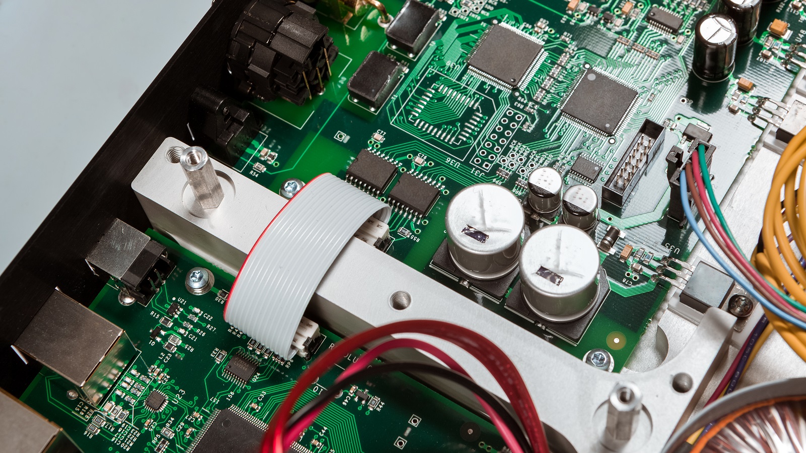
Key Features
Compact Size: PCB relays are among the smallest relay types, perfectly suited for through-hole mounting on printed circuit boards. This design maximizes space efficiency while ensuring mechanical stability.
Galvanic Isolation: One of the standout features of PCB relays is their ability to provide galvanic isolation between control and load circuits. This enhances safety by preventing unwanted electrical interactions.
High-Voltage Handling: While designed to handle substantial voltage and current loads, PCB relays are versatile and applicable in both AC and DC systems.
Thermal and Frequency Protection: Some PCB relays, especially solid-state ones, feature thermal trip settings and frequency protection that help protect the circuits from environmental and operational stresses.
How PCB Relays Work
PCB relays are designed on a principle of electromagnetic induction. The most important constituent part is the electromagnetic coil that, if energized, produces a magnetic field. This resultant magnetic field actuates a metal armature to change the contact state of the relay-that is, either connecting or disconnecting-to manage the load circuit.
Internal Mechanism
Coil and Armature: This coil develops a magnetic field to shift the armature, thus changing the contact position.
Contacts: These include normally open and normally closed, which, as the requirement arises, connect or disconnect the circuit.
Spring and Yoke: These parts return the armature back to its original position by removing the magnetic field. Operation of PCB relay requires perfection in design and implementation since it requires alignment and maximum efficiency of coil and yoke without distortion.
Type of PCB Relay
Based on Poles and Throws
SPDT (Single Pole Double Throw): It controls one circuit along the two positions of switching, hence versatile for toggling between two states.
SPST (Single Pole Single Throw): It controls one circuit and has a straightforward on/off operation.
DPST (Double Pole Single Throw): This manages two independent circuits but with one switching mechanism.
DPDT (Double Pole Double Throw): In essence, this contains two SPDT relays packaged in one, enabling the control of two different circuits or states simultaneously.
Based on Operating Principle
Electromagnetic Relays: These use an electromagnet to actuate mechanical contacts, providing robust and reliable switching for both AC and DC applications. The electromagnet creates a magnetic field that opens or closes the contact sets based on input voltage levels.
Solid-State Relays: These relays use semiconductor devices for switching instead of mechanical parts. SSRs have the advantage of switching fast, durability, and no noise. They allow isolation using optocouplers, hence safety, while maintaining fast signal processing.
Thermal Overload Relays: Utilize a bimetallic strip that bends with the change in temperature. The resulting movement actuates the relay contacts, which, by opening or closing the circuit, provide protection against overheating due to temperature fluctuations.
Hybrid Relays: Combine elements of both electromagnetic and solid-state types in an effort to realize advantages of both. Hybrid relays commonly use a fast-switching SSR for the low-level function and a larger, more robust electromagnetic relay for switching the larger load, so the benefit of precision and high power capability can be realized.
Best Practices for Mounting and Testing
Careful attention to mounting and testing a PCB relay is necessary to ensure top performance and reliability.
Mounting Techniques
Material Selection: For through-hole mounting, 1.6mm thick PCBs are recommended, usually made with glass or paper epoxy for strength and resistance.
Soldering Process: Soldering should be done with precision. Guidelines say to use a 30-60W soldering iron at a temperature of about 350 °C, so that the connections are proper but not damaged thermally.
Placement: Place relays away from heat-emitting components like resistors and transformers and sources of vibration to avoid mechanical failure.
Testing Procedures
Effective testing involves several steps to confirm operational readiness:
Continuity Testing: Use a multimeter to verify contact continuity and switching action. In an unenergized state, test for connectivity between NC contacts and for the lack of continuity with NO contacts.
Energized Testing: Power the relay and listen for a clicking sound, indicating successful switching from NC to NO contact positions. Confirm continuity between NO contacts and poles during this energized state.
Resistance Measurement: The coil resistance should be measured to ensure that it falls within the manufacturer's specifications.
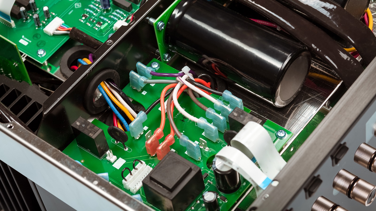
The PCB relays form a critical part in modern electronic systems for control and protection purposes. With their compact designs, highly reliable operations, and capability of handling substantial power with galvanic isolation, they can be applied to several applications. With types, principles of operation, and best practices for integration in mind, designers can expand the performance and life expectancy of their systems. Mount carefully and follow thorough test protocols to ensure that PCB relays will continue to deliver efficient and safe control for innumerable circuit designs.
Hot Tags:
Contact us

If you can't find what you're looking for, please contact us.
Article
Carrier PCBs are crucial for data modulation, multiplexing, and network integration, supporting efficient and robust telecom infrastructures globally.

DIP switches, cost-effective and manual, enable easy configuration of device modes, offering flexibility and simplicity for various electronic applications.

Amplifier PCBs enhance audio signals in devices like headphones and theater systems using components like transistors and capacitors for clear sound.