Printed Circuit Board Materials
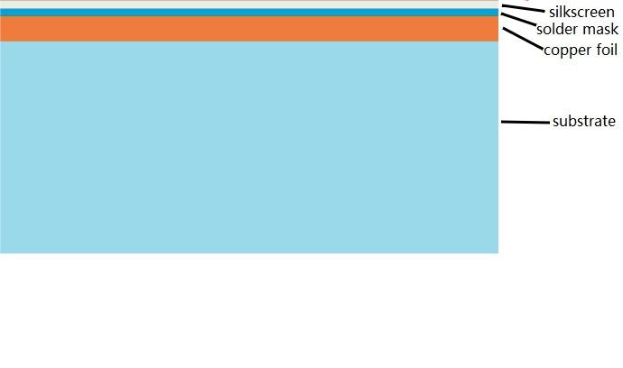
PCBs (Printed Circuit Boards) are fundamental in electronics, composed of multiple layers like silkscreen, soldermask, copper, and substrate, chosen for specific electrical functions.
What is a PCB?
The Printed Circuit Board (PCB) is one of the most important components of any electronic component, often known as the printed wiring board or printed wiring card, serving as the basis of devices from computers and calculators to other complex, non-compute-based electronic systems; thus its material composition must be carefully chosen based on the electrical function that it will perform.
Before the invention of PCBs, crossed wires were typically used for circuit assembly, which led to circuit jams, failures, and short circuits over time. The hand wiring process was exceedingly labor-intensive and complex. Printed circuit boards were mainly created as a result of the need for circuit designs to have a simpler solution with the advent of the electronic era. This advancement made it possible to efficiently exchange circuits between different parts. Solder is the metal that functions as glue and conducts current.
Composition of PCB Material
The general composition of a Printed Circuit Board consists of four Layers, which are Heat-laminated to form a single layer. They are as follows:
1. Silkscreen
2. Soldermask
3. Copper
4. Substrate
Substrate Layer
The substrate layer normally uses a fiberglass impregnated with an epoxy resin called FR4, where "FR" stands for "fire retardant." It is a strong framework for PCB, and its thickness depends on the intended use. Other substrates used on lower-end boards include phenolics or epoxies, which are more likely to heat shock and delamination. These boards can be recognized by the distinct odor they release after soldering.
Copper Layer
The second layer is copper, which is attached to the substrate using heat and adhesive. This layer of copper is usually thin, and some PCBs have copper on both sides of the substrate. Copper single-layer PCBs are normally found in more inexpensive electronic devices.
Copper Clad Laminate (CCL)
Copper Clad Laminate is used in most printed circuit boards and can be classified, according to different standards:
- Reinforcing Material
- Resin Adhesive Used
- Flammability
- Performance Characteristics
These classifications help in finding out the most appropriate CCL for an application.
Users are able to understand why printed circuit boards are one of the most important components of modern electronics and how their designs have been adapted to satisfy the rapidly advancing needs of technology by studying these basic principles and material constitutions.
| Classification Standard | Material | |
| Reinforcing Material | Paper base class | PF resin (XPC, FR1, FR2) Epoxy resin (FE-3) Polyester resin |
| Glass fiber cloth base class | Epoxy resin (FR4, FR5) | |
| Composite epoxy material (CEM) | / | |
| Lamination multilayer base class | / | |
| Special material base class | BT, PI, PPO, MS | |
| Flammability | Flame-proof type | UL94-VO, UL94-V1 |
| Non-flameproof type | UL-94-HB | |
| CCL Performance | CCL with ordinary performance | / |
| CCL with low dielectric constant | / | |
| CCL with high heat resistance | / | |
| CCL with low coefficient of thermal expansion | / | |
Above the green solder mask is the silkscreen layer, which includes letters and numerical indicators that make a PCB readable to technicians and programmers. This layer enables the professionals in charge of the assembly of electronics in uniquely aligning each PCB and correctly inserting it in various components. This silkscreen is generally white, but it can also be red, yellow, grey, or black.
Material Selections Affecting Cost
Features like gold tabs, blind or buried vias, or via filling increase the cost of a PCB. Similarly, line/width spacing lower than 6 mils increases the cost for the same reasons. More specialized processes are needed to make such small PCBs. Some fabricators are capable of line/width measurements as small as 3 mils, though this should not be used in most cases unless the component called for demands it.
Power and Heat Influence on PCB Material Selection
Power and heat are two of the most vital parameters influencing a PCB. Thermal conductivity tends to determine how efficiently a board turns power into temperature over the length of the material. Whereas industry-wide values for thermal conductivity do not quite exist, many materials are generally known for their specific thermal properties.
For example, Rogers Corp.'s RT/droid 5880 is commonly used in EW and communications applications requiring a low dielectric constant and reinforced with micro-fibrous glass components. Poor thermal conductivity, on the other hand, is a significant drawback for a wide range of heat-intensive applications despite its good performance in high-frequency applications.
PCB Materials and Industry Applications
PCBs are fabricated for a wide array of usage within many industries: military, aerospace, automotive, and medical fields. They use both single-sided and double-sided variants. Some are copper-cladded, while others have aluminum. Each industry picks the core for its PCBs according to the performance they want to achieve. This includes:
Lightweight: Aerospace applications require low mass, as do some in the automotive field.
High Power Handling: This is necessary in applications requiring high, safe power and reliability.
When selecting raw materials for PCBs, several performance indices must be compared to the application to ensure that the level of raw material utilized is consistent with the desired performance.
Flexible and Rigid-Flexible Boards
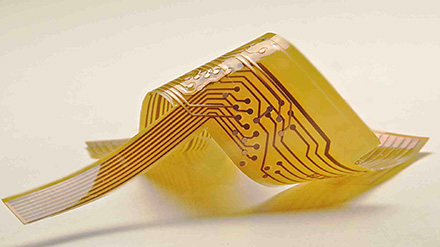
Flex and rigid-flex boards have become quite popular due to their vast range of applications. The board may be folded, bent, or wrapped around any object, allowing it to perform functions that a flat circuit board cannot. For example, a flex board can be utilized in equipment that requires it to fold at an angle while preserving electrical connectivity without the need for extra connecting panels.
Kapton in Flex Boards:
Most flex boards are made of polyimide film developed by DuPont Corporation, known as Kapton. The material has excellent heat resistance, and dimensional stability, and its dielectric constant is 3.6.
There are three Pyralux versions of the Kapton:
- Flame Retardant, FR: Makes it difficult to burn.
- Non-Flame Retardant, NFR: For standard use without flame retardant.
- Adhesive-less / High Performance, AP: Enhanced performances are reached in an adhesive-free product.
Hot Tags:
Contact us

If you can't find what you're looking for, please contact us.
Article
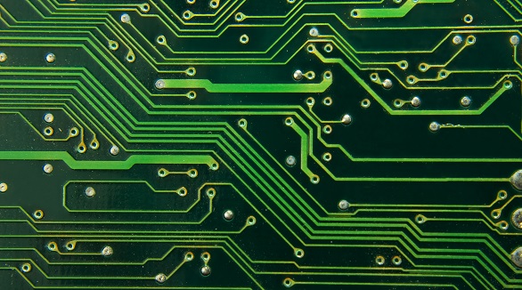
Single-sided PCBs are cost-effective, easy to design and manufacture, quick to produce, reliable, and eco-friendly. Ideal for low-density circuits and simple applications, they offer faster debugging, lower assembly complexity, and reduced short-circuit risk.
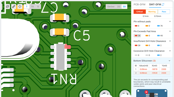
The article is developed concerning the breakthrough of integrated circuits and the need for custom PCBs in some electronic products. It enumerates ten golden rules in conducting PCB layout design and manufacturing: grid selection, routing, power layers, component placement, panel duplication, component value combination, frequent DRC, flexible silkscreen use, decoupling capacitors, and pre-production parameter checks. These rules provide for the optimum design and manufacturing of a PCB.
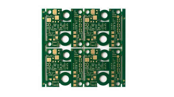
Most electronic circuits are mounted on PCBs, or Printed Circuit Boards, which provide mechanical support and electrical interconnection of electronic components. There are, however, special applications that involve the use of single and double-sided PCBs, multi-layer PCBs, or even rigid and flexible PCBs with aluminum backing, targeting medical, industrial, auto, and aerospace industries. They may use materials such as fiberglass, epoxy, aluminum, and others.
