SMD Chip Removal with Hot Air
Mastering hot air rework to remove SMD chips ensures precise control, protects the PCB, and is vital for effective electronics repair and upgrades.
SMD components, which include chips and ICs, have become standard in the fast-changing world of electronics due to their compactness and efficiency in electronic devices. Removing such components is an important skill for any person engaged in electronics repair or upgrades of smartphones, computers, or other high-tech equipment. Compared to all the available methods, hot air is exceptionally precise and controlled. It is an essential technique in professional work and even among do-it-yourself electronics.
A complete guide on how to safely and effectively remove SMD chips with a hot air rework station is explained herein. Understanding this technique is very important for ensuring the integrity of the PCB and extending the lifespan of the device.
Importance of Removing the SMD Chip in Modern Electronics
SMD chips are soldered directly onto the surface of printed circuit boards without using through-hole technology. This surface mount technology allows for more compact designs but requires special methods for repair and replacement of components because they are very fragile.
Knowing how to remove SMD chips is important for several reasons, such as conducting repairs, upgrading old components, or recycling and salvaging valuable electronic parts. As sizes go smaller and capabilities get larger, a person's ability to handle the SMD component with precision becomes more important.
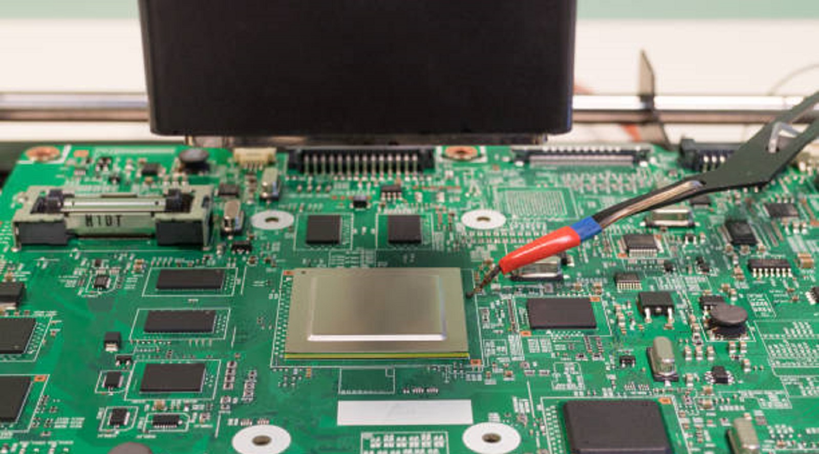
Why Hot Air is Preferred for SMD Removal
Precision: Hot air rework stations allow for precise temperature control and airflow management, minimizing the risk of unintentional damage to the PCB or nearby components.
Versatility: These stations can handle a wide range of electronics and component sizes, from small resistors to larger ICs, making them indispensable in diverse repair scenarios.
Time Saved: Hot air increases the effectiveness of the method used for de-soldering and will eliminate any residual leftovers that are held on to some components. Also, with proper technique, ensure the desoldering of component parts in place.
Non-Contact Method: No physical contact required at the surface since the method relies on air blasts for SMD chip removal compared to the case with soldering irons.
Tools and Equipment Needed for SMD Chip Removal
To ensure effective and safe SMD chip removal using hot air, gather the following tools and equipment:
Hot Air Rework Station: Should provide for temperature and airflow controls
Flux Pen: This tool assists with uniform application of flux to create easier melting soldering and reduces oxidation.
Fine Tip Tweezers: Useful to handle SMD components by using fine tips after the solder melts, without displacing the same
ESD Safety Gear: wrist straps and anti-static mats ensure sensitive components will not be discharged through electrostatic build-up.
Desoldering Braid or Pump: Used for cleaning residual solder from PCB pads.
Magnification Tools: Optional, but useful for precision work on small components, ensuring thorough cleaning and inspection.
Step-by-Step Guide for Removing SMD Chips with Hot Air
Prepare Your Workspace: Ensure your work area is clean, organized, and ESD-safe. Position all necessary tools within easy reach, and ensure your workspace is well-ventilated to manage fumes.
Hot Air Station Setup: Turn hot air rework station to a temperature of between 350°C to 380°C (662°F to 716°F). This is usually a good range for the job but might need to be adjusted depending on the flux type used for soldering the PCB. Airflow should be minimum to avoid moving other components in the vicinity without denying a proper heat application.
Add Flux: Use the flux pen to apply a small amount of flux around the circumference of the SMD chip. This promotes even heat distribution, aiding the solder's transition to a molten state.
Heat the SMD Component: Position the hot air nozzle approximately 5-10mm above the chip. Move the nozzle in small circular motions to ensure even heating of both the component and the solder joints.
Monitor the Solder: Closely observe the solder joints for signs of melting. As the solder becomes shiny and fluid, it indicates readiness for removal.
Carefully Remove the SMD Chip: Once the solder is sufficiently melted, use tweezers to gently lift the SMD chip. Apply steady, gentle pressure to avoid damaging the PCB or lifting the pads.
Clean the PCB: Use a desoldering braid or pump to remove any excess solder, preparing the area for a new component placement or further repairs. Cleaning ensures a smooth, conductive surface for future soldering.
Inspect and Test: With the aid of magnification tools, inspect the cleaned area for any potential damage, such as lifted pads or bridged connections. Conduct standard electrical tests on the board to confirm the integrity of the remaining components.
Considerations and Potential Pitfalls
Temperature Control: Avoid heating excessively as SMD components will get damaged. The use of foul fumes could be hazardous if not properly ventilated and taken precautions with.
Precision Handling: Let the hot air tool be handled securely and make sure it does not come into contact with the PCB because any accidental contact with it can cause damage.
Post-Removal Testing: Testing the functionality of surrounding components post-removal is essential to ensure successful repair without collateral damage.
Advantages of Hot Air Rework Stations
Hot air rework stations are favored in the electronics repair industry for their flexibility, ease of use, and precision. They not only function as primary tools for soldering and desoldering tasks but also allow for efficient workflows when handling intricate electronic repairs. Moreover, the non-contact nature of their operation reduces the risk of heat-related damage during repairs.
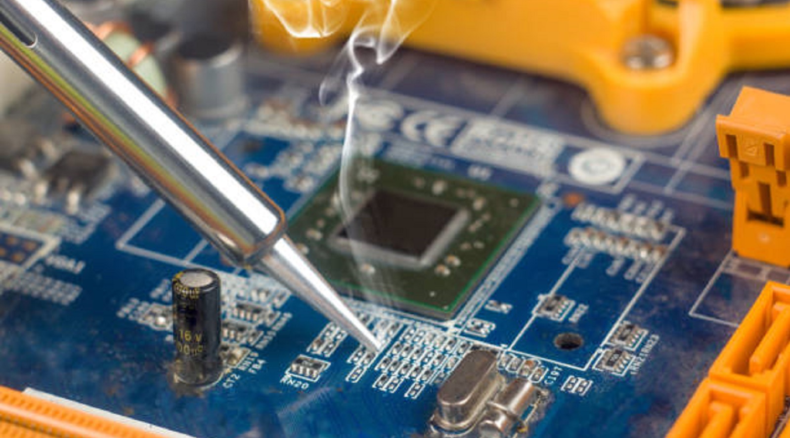
Proficiency in hot air SMD chip removal techniques is, thus, quite critical to any individual either working with electronics repair or maintenance. This in return makes sure that devices are efficiently and reliably repaired, products will last longer, and performance is revitalized. Practice, patience, and attention to detail, along with the right tools and safety precautions, will be some of the ways to successfully handle SMD components, making this technique essential in modern electronics repair.
Hot Tags:
Contact us

If you can't find what you're looking for, please contact us.
Article
Achieving PCB stability involves balancing design precision and costs through techniques like GD&T, balanced stack-ups, and even metal distribution for reliability.
Routine inspections and proper maintenance of capacitors and resistors in PCBs reduce failures, prolong device lifespan, and lower maintenance costs.
The article provides a step-by-step guide to soldering a PCB, covering workspace setup, essential tools, and safety measures. It explains heating the soldering iron, applying flux, tinning the iron tip, placing components, heating joints, applying solder, cooling, inspecting, and cleaning. Emphasis is on practice and safety for successful soldering.
