- Products & Capabilities

- Simulation Design & EDA

- About
- Resources
Significance of AOI in SMT Assembly


As PCB lines and components shrink, traditional visual inspection fails; AOI using DRC and CAD methods is crucial for quality SMT assembly, offering intelligent, accurate inspections.
As the lines on PCB (Printed Circuit Board) intended for SMT (Surface Mount Technology) assembly continue to shrink, along with components becoming miniaturized, and SMD (Surface Mount Device) more densely packed, the original visual inspection methods can not meet the quality demands. In turn, AOI (Automated Optical Inspection) has become a very important technology in SMT assembly for the inspection of solder joint performance. The increasingly applied and technologically developed AOI tends to intelligent inspection modes in SMT assembly.
Working Principle of AOI Technology
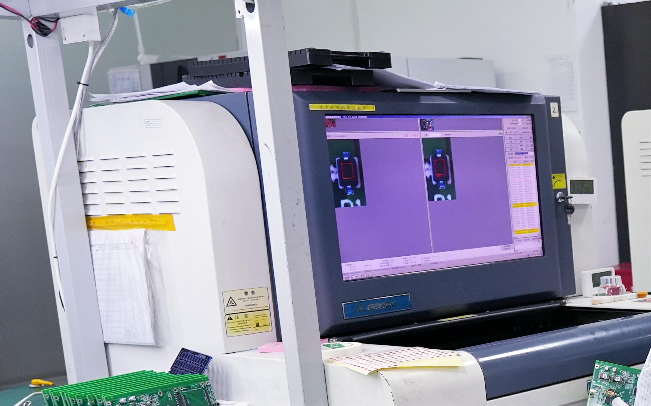
Despite the various forms that AOI can take in SMT assembly, generally, they share a common underlying technique, and that is the process of using optical techniques to capture images of the target to be inspected and analyzed, and judged based on some criteria. The commonly used methods in AOI systems are DRC (Design Rule Check), and CAD (Computer-Aided Design) data comparison.
DRC
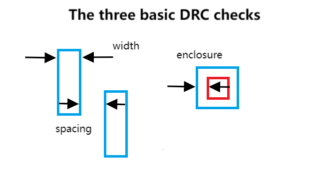
The DRC method applies inspection to design patterns according to predetermined rules. For example, a PCB circuit pattern can be checked to ensure that all lines end at solder joints, have the same width, and that their positioning concerning each other lies within a distance. In this manner, the DRC method could achieve that the algorithmic validity of the pattern is secured and some benefits, including easy setup, high-speed performance, minimum program, and insignificant data storage. Thus, this method is extensively used in AOI systems.
However, the DRC method's limitation lies in its ability to determine boundaries, thus requiring particular methods to establish boundary positions.
CAD Data Comparison
Compared digital image patterns stored in the AOI system to real captured images this method could develop the inspection results. The accuracy depends on inspection precision, definition, and all the steps involved in the inspection, which means the method is highly concerning accuracy but requires high data storage and real-time behandeln capabilities.
Although both techniques have advantages, the CAD data comparison method is chosen more for its gains in a wide range.
Inspection Functions of AOI Technology
AOI is applied in inspecting bare PCBs, solder paste printing, components, and solder joints.
In the production process, bare PCBs and solder joint inspections are usually done by separate AOI equipment, which inspects in a non-real-time manner.
An AOI system often integrates solder paste and component inspection into one, including real-time inspection with solder paste printers and chip mounters. An example would be the advanced solder paste printer with two heads, capable of real-time inspection of the printing thickness and the edge collapse through AOI systems.
Inspection items:
Disconnection, wire-tapping, scratches, pinholes, mass-area defects, line space, and trace, edge roughness, for bare PCBs.
Lead formation and bending of solder joints, missing components, misplacement, orientation of components, solder joint quality, etc.
If AOI system detected unqualified components, they would usually give reminders to operators for replacement, which could help to prevent big mistakes.
Structure of Common AOI Systems
AOI System for Bare PCBs
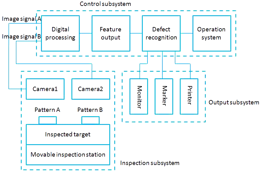
This system has a comparison function and two cameras. The 1D image sensor installed in the inspection subsystem photographs the images of the traces of the PCB. After correcting and high-speed A/D transforming, it sends the signals to the control subsystem to decide the defects, scanning by moving the inspection station linearly to offer the 2D image output signals. After detecting some defect, it allows real-time marking and a magnified display in the monitors, thereby easing off the judgment of vision.
This system operates interactively through a monitor, with digital and real image monitoring, as well as a printer and a synchroscope, allowing digital and real images to be displayed or printed, and the image signal figures and the digital clip levels can be observed by a synchroscope. The inspection speed is several meters per minute, with a resolution at the micrometer level and minimum line width/spaces.
AOI System for Solder Joints
AOI for solder joints uses an optical camera for image capturing in 3D. After processing, the data is compared with standard images to detect and classify defects and their position.
AOI System for Solder Paste Printing
The overall system is comprised of a camera and an optical fiber x-y system. The x-y axes of the x-y table facilitate the imaging of PCBs, while an ideal condition in solder paste printing uses the paste corresponding to the thickness of the stencil. During this process, slant light is applied from the annular optical fiber and the annular reflector of the inspection system; the camera takes such images of the paste for measurement of the edges and the thickness of the paste, so the shapes are now converted into optical changes for checking.
AOI Services at PCBX
PCBX offers free AOI services for our customers who ordered PCBs and PCBA. X-ray inspection service is also provided to guarantee better quality and reliability of your products.
These free AOI services help manufacturers to get complete quality control over their SMT assembly process, thus increasing the performance effectively.
Hot Tags:

Contact us

If you can't find what you're looking for, please contact us.
Article
SMT assembly places components directly on PCBs, enhancing miniaturization, performance, and efficiency. Key steps: solder paste printing, chip mounting, reflow soldering, and inspection.
 2024/08/05
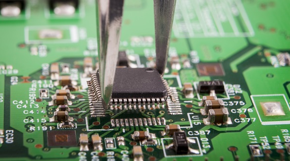
Still, SMT can further feature defects such as solder bridging, cold solder joints, tombstoning, and solder balling. Grasping the very common faults and their solutions is the key toward effective PCB assembly and reducing SMT errors—very much in line with the trend toward PCB miniaturization and higher component density.
2024/07/29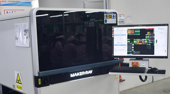
These SMT PCB assembly methods are involved, ensuring that several defects are detected. This includes the use of Automated Optical Inspection, In-Circuit Testing, and Automated X-ray Inspection. The combination of these methods is beneficial in facilitating an optimal inspection process.
2024/07/26