The Comprehensive Guide to Circuit Grounding
Grounding is essential in PCB design for safety and stability, providing a path for excess current, protecting equipment, stabilizing voltage, and reducing EMI, thus ensuring reliable device operation.
One of the most basic concepts in electrical and electronic systems is grounding, both a safety measure and a means of ensuring that different groups of equipment work perfectly. In the panorama of PCB design and manufacturing-precision and reliability being key factors-the importance of grounding can be underlined even more. At PCBX, we value the notion of grounding highly enough to make it a cornerstone within our design procedures. This article looks deeper into the concept of grounding, how it works, and also plays an important role in the protection of electrical systems.
The Basics of Grounding
Grounding is a safety measure that provides a direct path for excess electrical current to reach the earth harmlessly, preventing electrical shock or even fires. Commonly, it is done by attaching a wire from the circuit into a conductive rod inserted into the ground. A system like this ensures that when electrical systems have an excess of voltage, that excess is harmlessly dissipated into the earth.
Grounding, however, occurs in a number of different forms: earth ground, chassis ground, digital ground, and analog ground-necessary each in its respective location. Earth ground is equally very important, with the process concerning the connection of circuit parts to a non-variable, neutral point-usually with the assistance of conduction materials such as copper. The invariable reference point ensures a smooth and steady supply of current with less vulnerability to the risks of voltage fluctuations.
Why Grounding is Important
The chief advantage of grounding is safety. It just avoids situations-which could otherwise lead to electric shock or fire-since it provides a low-resistance path to ground for excess electricity. In residential, commercial, and industrial applications, respectively, grounding reduces risks related to electrical surges and malfunctioning electrical circuits, making them inherently much safer to operate.
Another important benefit is the protection of electronic equipment. Grounding stabilizes voltage levels across circuits, which is very important in preventing damage to sensitive equipment through unexpected voltage spikes. This protective function increases the service life of electronics and reduces the costs associated with maintenance, along with improving overall reliability.
Additionally, grounding improves the efficiency of power distribution. By providing a uniform reference point, it prevents overloading of circuitry and allows electrical devices to function within their limits, thereby facilitating stability in everything from home appliances to industrial machinery.
How Grounding Works
In standard electrical systems, there are three wires: hot, neutral, and grounding wires. The hot wire supplies the electrical current, while the neutral wire offers the path of return to complete the circuit. Under normal circumstances, the grounding wire does not carry any current but plays a very crucial role in safety. On malfunctioning of a circuit, the grounding wire offers a harmless path for stray currents, redirecting them to the ground and protecting against the chances of electrical shock or fire hazard.
Grounding can also be understood to represent smoothening effect, as it provides a reference point that prevents voltage from changing wildly. This reduces electromagnetic interference, which might otherwise interfere with normal circuit and device operation.
Practical Steps to Effectively Ground a Circuit
Circuit grounding for effectiveness is done in the following way:
Locate and Identify the Ground Point: Any circuit drawing should include a ground point identified by its own type of symbol. This would serve as the reference for an entire grounding system.
Connect with Good Conductors: Copper wires, for example, would be connected from this point to a well-embedded copper grounding rod into the earth. The connection must result in minimal resistance to effectively handle any electrical discharge.
Ground Planes on PCBs: In every complex PCB layout, a copper plane running across the board continuously acts to reduce electromagnetic interference, hence signal integrity.
Star Grounding in Complex Systems: In cases where there is a need to avoid ground loops, a star grounding method is recommended for all grounding connections to a single point, thereby canceling any probable interference.
Regular Testing: Establish on a periodic basis circuit testers that will serve the purpose of checking whether or not the grounding system operates. The testers can detect any mismatch between voltage levels of hot, neutral, and ground connections, so the system is safe.
Ensuring Proper Grounding Detection
Whether proper grounding can be determined visually or by the use of technology, such as in circuit testers. A three-prong outlet-the third prong basically an indication of grounding-is indicative, but not conclusive, without further testing. A circuit tester will directly test the integrity of the ground connection by looking at discrepancies in electrical flow.
In addition, it ensures professional inspection of the grounding for continued effectiveness, which may be in question in older systems where the wiring could deteriorate with time.
Built-in Safety Devices
A number of built-in safety devices in modern electrical systems, including fuses and circuit breakers, complement grounding. Such devices play a critical role in:
Surge Protectors: Buffering the systems against unexpected voltage increases.
Circuit Breakers: These automatically disconnect a circuit in the case of overload or short circuit and therefore prevent potential damage.
In addition, the grounding framework connects other conductive elements such as plumbing that offers extended safety against errant voltages.
Conclusion
Grounding is one of the most crucial aspects for all electrical or electronic systems. It represents the safety cover necessary at sudden surges of power, therefore making sure all the devices that are around the circuit work within their prescribed parameters. Proper grounding involves quite a few complex features while considering careful planning and execution, regular testing, and continued attention to detail.
At PCBX, we implement comprehensive grounding on advanced PCB design while ensuring that our customer's product attains the highest standards of safety and functionality. We address the issue of safety with the implementation of safe and effective grounding into each design, enabling our customers to make products that operate reliably and innovatively in different electrical environments.
Hot Tags:
Contact us

If you can't find what you're looking for, please contact us.
Article
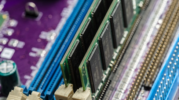
Backplane PCBs support functional boards, distribute power, and transmit signals. Increased IC complexity demands more layers and high performance, creating challenges in alignment, drilling, electroplating, ICD issues, and stub management. Tips include precise alignment control, advanced drilling and plating techniques, and maintaining stub lengths below 0.25mm for optimal signal quality.
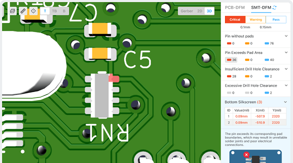
The article is developed concerning the breakthrough of integrated circuits and the need for custom PCBs in some electronic products. It enumerates ten golden rules in conducting PCB layout design and manufacturing: grid selection, routing, power layers, component placement, panel duplication, component value combination, frequent DRC, flexible silkscreen use, decoupling capacitors, and pre-production parameter checks. These rules provide for the optimum design and manufacturing of a PCB.
Thermal management is all about more than just keeping the temperature of electronic systems and printed circuit boards low. It has been a key issue related to reliability and performance. Of the very basic fundamentals that would be studied in the field, some are concerned with methods of heat transfer. These are through conduction, convection, and radiation. The methods of cooling include natural cooling, forced-air cooling, fluid cooling, and evaporation cooling. Appropriate thermal design rules shall be followed wherein the chosen materials provide optimum thermal conductivity and the components of a system are so laid out that no hot-spotting will take place. Thermal analysis becomes critical in pointing out heat-related issues and optimizing the design. It thus minimizes failure rates and enhances stability and functionality of the electronic systems through comprehensive thermal management.
