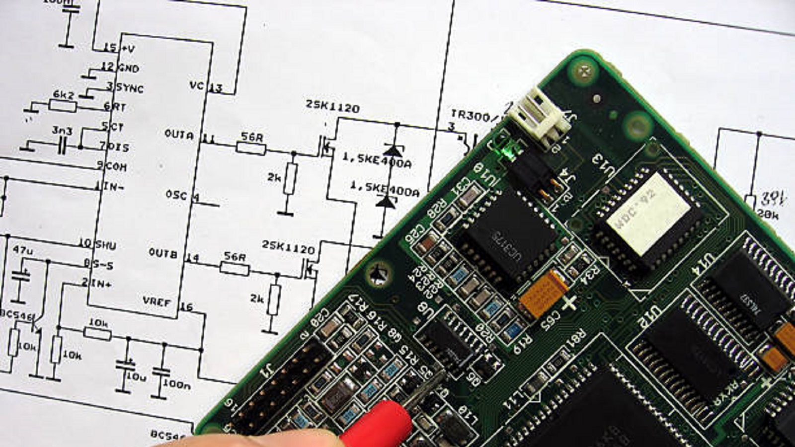
What is Schematic Diagram?
Schematic diagrams use standardized symbols to illustrate electronic circuits, essential for design, analysis, and construction, bridging concepts and reality.
Schematic diagrams are a way of showing how a circuit works and its connectivity in an electronic device. A two-dimensional drawing describes the interrelationship of components at the electrical level using standardized symbols. Understanding a schematic diagram forms the basis of any professional or hobbyist who intends to design, analyze, or construct electronic devices.
The schematic diagram is a more detailed drawing that represents the elements and interconnections of an electronic circuit using symbolic representations. Some common diagramming symbols used in electronic schematic diagrams include electronic symbols, wiring diagrams, designators, net names, and netlists that make the communication of electronic circuit designs straightforward. Mastering schematic symbols is very critical for a PCB designer, as these symbols put complex physical and electrical properties into a language understood across the board.
Differentiating Schematic Diagrams from Schematic Block Diagrams
Schematic diagrams cover detailed connections and components, while schematic block diagrams show the system or process in a high-level way. A block diagram simplifies detailed systems with the use of labeled blocks for various elements or stages in a system, showing how they are interconnected and their flow of signals. This gives clarity in the understanding of system functionality and organization without going down to the minute details of system composition.
Key Elements of Schematic Diagram
Schematic Component Symbols: Schematic diagrams use symbols to represent component characteristics and functions in simplified ways. For instance, resistors are represented by a zigzag line to indicate that they resist the current flow, while capacitors are represented by parallel lines with space in between, showing the storage capability for electricity. These intuitive symbols provide instant recognition and identification of components in the circuit.
Reference Designators: All schematic components shall carry a reference designator, such as R for a resistor, C for a capacitor, followed by a sequential order, like R1, C2, etc. It is important in that it maintains coherence and order in the diagram per se and communicates clearly and directly with the BOM. The BOM will enumerate the parts and define their location for installation based on the designators for easier assembly and manufacturing.
| Letter Code | Component |
| R | Resistor, Potentiometer, Rheostat |
| C | Electrolytic Capacitor, Non-polarized Capacitor |
| L | Inductor |
| D | Diode, LED, Schotty Diode, Zener Diode |
| Q | Transistor, MOSFET, JFET |
| U | Integrated Circuit IC, Op-amp, Microcontroller |
| BT | Battery |
| S or SW | Switch |
| T | Transformer |
| F | Fuse |
| J | Connector |
| Y | Crystal, Oscillator |
| K | Relay |
Symbol Attributes and Values: Additional information is provided with the symbols so that the right component is selected. The values include the specific ones such as resistance in ohms (Ω), capacitance in farads (F), while the operational attributes include tolerances and maximum conditions. Other attributes include manufacturers' part number, tolerance, and package code for the precise identification and selection of components.
Schematic Standards
Schematic diagrams are drawn based on generally accepted norms for regularity and simplicity: two such norms are the IEC 60617 or International Electrotechnical Commission and ANSI Y32 or American National Standards Institute. Both these institutes have developed the graphical representation for the depiction of various electronic components. Both the mentioned institutes provided an extensive library of symbols, starting from passive components and active devices to the power source, which is continuously getting updated with newer releases to add recent developments in technology and the requirements of time.

Schematic diagrams are essentially instructional or working drawings for any PCB designing. Designers are allowed to see the general disposition of a circuit, test their designs by simulation, and verify functionality before the actual physical construction, saving cost and time in the process. When troubleshooting is required, the schematic diagram is used to go through the job efficiently in order to search for faults and to perform the repairs; that again underlines their important role in maintenance and repairs, too. The art of reading and creating schematic diagrams lets professionals innovate, troubleshoot, and confidently and effectively deliver designs.
With the velocity of technology development never seen before, schematic diagrams remain an essential skill for amateur and professional alike. As we continue to strive for what is thought impossible, the schematic diagram will remain the necessary link between conception and reality in the ever-changing world of electronic design.
Hot Tags:
Contact us

If you can't find what you're looking for, please contact us.
Article

Power and ground planes in PCBs ensure signal integrity, manage heat, and minimize EMI, crucial for efficient, high-performance electronic devices.

Designing PCBs for IoT demands innovation to tackle space, power, connectivity, and security challenges, ensuring robust, efficient, cost-effective devices that meet modern technological demands.

High-speed PCBs (>1GHz) are crucial for advanced electronics like 5G and data processors. Key practices include ensuring signal integrity, controlling EMI, and maintaining power integrity for reliable performance.
