- Products & Capabilities

- Simulation Design & EDA

- About
- Resources
What is the Difference Between SMT Assembly and THT Assembly?


Printed Circuit Board Assembly (PCBA) employs Through-Hole Technology (THT) and Surface Mount Technology (SMT). THT offers robust mechanical bonds, ideal for high-stress applications, whereas SMT supports efficient, high-density assemblies. Each method has unique advantages and limitations, impacting cost, manufacturing efficiency, and component compatibility. Understanding these differences is key for optimal PCB design.
Printed Circuit Board Assembly (PCBA) is essential to connecting electronic components with bare PCBs for the completion of desired electrical functions. Within the PCB assembly itself, there are two dominant methods: Through-Hole Technology and Surface Mount Technology. These types of assembly have their own advantages and applications, greatly impacting manufacturing efficiency, cost, and component compatibility. The following discussion tries to delve into the details of both these methods so that it can be clearly understood wherein the differences lie between them and what benefits and limitations they hold for the user.
Through-Hole Technology (THT)
Definition and Process
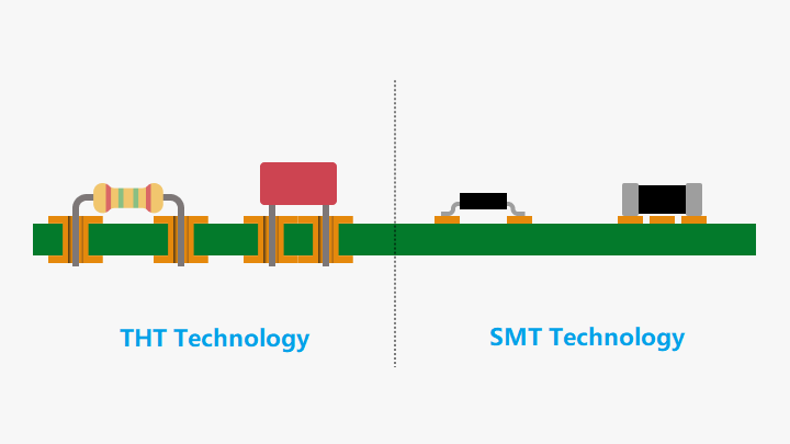
The procedure is one where the component leads are inserted into the holes previously made in the PCB. These leads are soldered with the use of either a wave soldering technique or by hand. The reasons for the successful implementation of this approach are the strength in the mechanical bonds created through the through-hole solder joints.
Applications
THT components are generally used for high-reliability and durability applications, particularly in those that experience extreme physical stress, like those in military and aerospace applications, or heavy industrial uses that could see extreme acceleration, vibrating with intensity, or extreme temperatures. Another place where THT really excels is in the prototype and test arena, where manual adjustments and replacement are more common.
Component Types
Generally, there are two varieties of through-hole components:
- Axial lead Components: The wires protrude from both terminals of the component and hence, make the component lie flat over the PCB.
- Radial Lead Components: The wires protrude from one terminal of the component and thus, make the component stand on end over the board.
- Radial leads often tend to save space and thus are preferred in dense board layouts. The axial leads seem to have the flexibility in lead spacing.
Advantages and Disadvantages
Advantages:
Strong Mechanical Bonds: The existence of leads physically through the PCB gives strong mechanical bonds. This is more relevant in components that are subjected to mechanical stress.
Easy for Prototyping and Testing: It is easier to replace or manipulate by hand through-hole mounted components when it comes to the prototyping and testing phases.
Disadvantages:
Time and Cost Increase: It takes much time and resources to drill holes for each component.
Limited Routing Space: Holes drilled take a lot of space in a multilayer PCB routing space.
Lower Efficiency: Due to the same reason cited in the above point, the wave or hand soldering accept less efficiency which makes the manufacturing process slower, inconsistent because of more/less soldering due to less solder in some cases, and differences in production.
Surface Mount Technology (SMT)
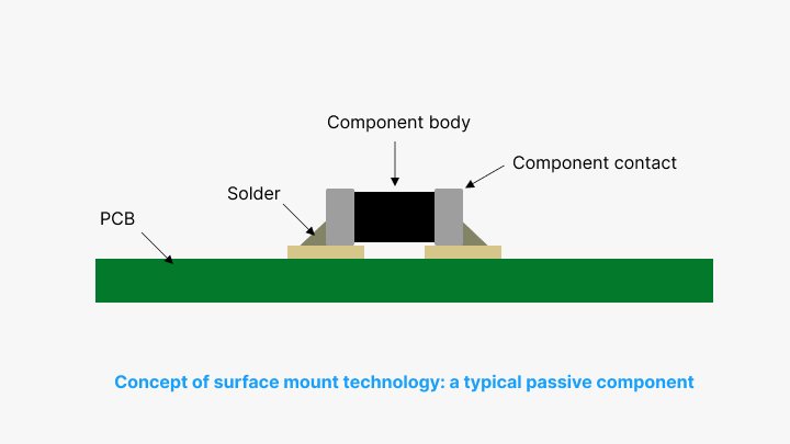
Definition and Process
SMT is a technology that mounts parts on the surface of the PCB directly. The components are called Surface Mount Devices (SMD), and they stick to the board using solder paste. The general SMT process includes the following; Solder paste printing, component placement, automatic optic inspection (AOI), reflow soldering, and post soldering inspection.
SMT was designed or developed in the 1960s but became popular in the 1980s. Nowadays, it is standard for most electronics due to its efficiency and support for high-density assemblies. Components are smaller and are allow designs on both sides of the PCB, making SMT quite suitable for small devices and miniaturized products.
Component Characteristics
SMDs have characteristics that best suit the modern day electronics. These characteristics include :
Shorter Leads: This will lead to more robust electrical connections.
Small Sizes: which allows it to take more components on that board.
High Reliability: as results of reflow soldering, because it produces robust and repeatable solder joint.
Advantages and Disadvantages
Advantages:
High efficiency since the production is done very quickly since the process is automated.
Design flexibility in that it accommodates high-density and double-sided components.
Saves cost since there is no drilling hence the price of the board reduces, and the production time is also less.
Has no board-to-board vulnerability due to reflow soldering; hence the long-term performance is enhanced even
Disadvantages:
Sensitivity to Environmental Stress: It may be true that it portrays relatively low environmental stress and thermal resistance.
Inspection and Repair Difficulty: It is quite evident that components with small dimensions are always difficult to inspect and repair.
Unsuited for High-Stress Components: It is very uncomfortable to use this arrangement for those components that carry high stress and utilize mechanical bonds for connection.
Comparison and Selection
Performance and Cost
Generally, SMT is faster and more cost-effective as a result of the automation in assembly and reduction in drilled holes. THT's time-consuming and manual nature increases the manufacturing cost and time.
Mechanical Strength
In case very strong mechanical bonds are required for the application, then the preference would be toward THT because the leads are mechanically anchored into the PCB. On the contrary, the surface bond in SMT is not suitable for high-stress components.
Component Density
SMT is most appropriate for applications requiring a high density of components and compactness; it also allows features to be placed on both sides of the PCB, thus offering maximum flexibility in design.
Applications Suitability
THT: Most suited for high-reliable products that operate in very harsh environments: aerospace, military, etc.
SMT: Most preferred for most commercial electronics that can achieve miniaturization and cost-effectiveness.
Hybrid Approach
In short, in some cases, combining THT and SMT delivers a balanced mix of robust mechanical connections from THT together with efficiency and compactness of SMT.
Conclusion
The state of the modern electronics manufacturing methodologies is served by both Through-Hole and Surface Mount Technologies, each dominantly excelling in parameters of their needs. Where the general characteristics of Through-Hole Technology dominate—such as components requiring strong mechanical bonds and durability under stress—some strength is there with Surface Mount Technology in respect of efficiency, cost-effectiveness, and suitability for high-density assemblies. An understanding of these strengths and limitations helps in making the right informed choice of assembly, ensuring better performance, reliability, and reduced cost of the electronic product.
Hot Tags:

Contact us

If you can't find what you're looking for, please contact us.
Article
SMT assembly places components directly on PCBs, enhancing miniaturization, performance, and efficiency. Key steps: solder paste printing, chip mounting, reflow soldering, and inspection.
 2024/08/05
Still, SMT can further feature defects such as solder bridging, cold solder joints, tombstoning, and solder balling. Grasping the very common faults and their solutions is the key toward effective PCB assembly and reducing SMT errors—very much in line with the trend toward PCB miniaturization and higher component density.
2024/07/29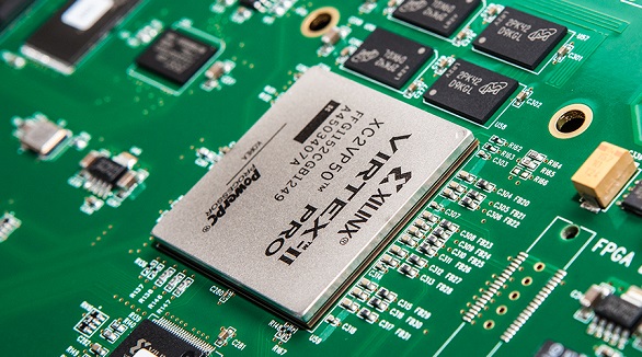
Ball Grid Array (BGA) components, such as PBGA, CBGA, CCGA, TBGA, and CSP, provide high I/O density, improved reliability, and high-quality electrical and thermal performance. Quality assembly and functionality are assured since advanced soldering and inspection methods are required, like AXI and AOI. Proper storage and handling shall guarantee the performance of the devices.
2024/07/26