- Products & Capabilities

- About
- Resources
What is the SMT Assembly Process?


SMT has transformed electronics manufacturing by enabling automation and miniaturization, leading to more efficient assembly processes and the production of high-quality, compact electronic devices.
Surface Mount Technology has transformed the electronics manufacturing industry. It is an efficient and cost-effective method of assembling printed circuit boards. We at PCBX understand that as technology develops rapidly, and miniaturization and complexity become everyday demands, SMT will increasingly play a significant role in manufacturing high-quality, reliable electronic products.
Understanding Surface Mount Technology (SMT)
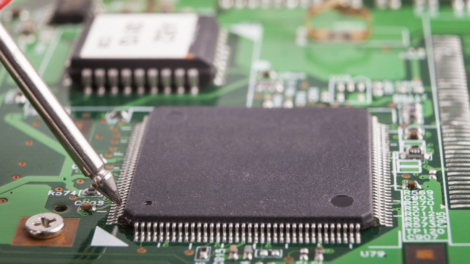
SMT is the process or methodology whereby the electronic components, now called surface mount devices or SMDs, are mounted to the surface of a PCB. The counterpart to that is through-hole technology, a more traditional method in which the component insertion into pre-drilled holes in the board is done. SMT facilitates automated production, which reduces assembly time and allows smaller and more complicated electronic devices.
Origins and Evolution
Originally called Planar Mounting, SMT was developed and patented by IBM in the 1960s for the assembly of small-scale computers. In the 1980s and 1990s, however, SMT gained widespread acceptance due to its facilitation of automated manufacturing and its amenability to miniaturized components. By this time, SMDs had gained significant penetration into most high-tech printed circuit assemblies, all but displacing through-hole technology in many segments of electronics assembly.
The SMT Assembly Process
SMT assembling involves multistage procedures, with much emphasis on precision and automation to ensure quality results. Now, let's look at the stages in detail:
Preparation of PCB and SMDs
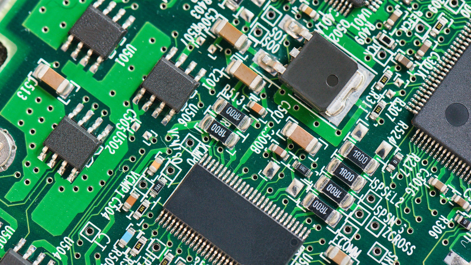
Basic preparation of a PCB and choice of SMDs mark the beginning of SMT assembly. The board is usually made up of flat copper pads, plated with solderable metals like tin-lead, silver, or gold, serving as points of attachment for the components. Stencils align these components accurately so that their proper positioning in the successive stages is ensured. It is worth ensuring that defects do not occur in these basic materials so an interruption to the assembly process is avoided.
Solder Paste Printing
The process involves spreading solder paste over the PCB using a stencil and squeegee. The solder paste is basically a mixture of powdered metal solder alloy combined with flux-a type of adhesive substance that helps hold the components in place, clean the surfaces of solder. Accuracy in the process is rather critical because slight misapplication can cause weak joints or bridges that could lead to functional failures. This is a step involving precision machinery and experience by the operators in applying just the right amount to each pad.
Component Placement
Following this, the SMDs are laid onto the PCB by automated pick-and-place machines. These types of machines use vacuum or gripper nozzles to pick components from reels and place them with a high degree of accuracy in their correct, assigned positions. Modern machines can place up to 80,000 components per hour. This greatly increases the speed of the assembly and reduces human error. The accuracy here is very important; wrong placing of the components may result in short circuits or extensive reworks at increased cost.
Reflow Soldering
After placing components on the PCB, it goes into the reflow oven for heating. Below is a diagram showing how the board passes through different temperature zones in the oven.
Preheat Zone: Board undergoes gradual heating to avoid thermal shock; temperature peaks at around 140 ℃ to 160 ℃.
Soak Zone: Temperature stays the same for its equal distribution in the board; about 60 to 90 seconds are required for this process.
Reflow Zone: Temperature reaches the peak between 210℃-230℃; solder paste is melted, and defect-free solder joints are created.
Cooling Zone: Solder is solidified through fast cooling to provide the desired and defect-free mechanical and electrical connections.
Reflow soldering is crucial in keeping the components securely on the board because any mistake in carrying out the temperatures may lead to defects such as voids, misalignment, or poor soldering.
Cleaning and Inspection
After soldering, the assembled PCB must be cleaned of flux residues. Sometimes, this stage is entirely skipped for no-clean processes; those use flux that can stay in place without causing any issues. This is the last check: AOI, X-rays, or sometimes just visual checks might be applied, depending on where a defect or misalignment has occurred. Having found any issues, rework stations correct them to have the PCB working as intended and reliably so.
Advantages and Disadvantages of SMT
Advantages
Miniaturization: SMT allows for smaller component sizes, thus enabling denser circuit designs and compact devices.
Automation: The process is highly automated, meaning that the associated labor cost and rates of error from manual assembly are low.
Flexibility: SMT provides double-sided PCBs that give more design flexibility and functionality.
Efficiency: The streamlined process translates to faster production times and accommodates large-scale manufacturing.
Cost-Effective: Lesser material consumption and better efficiency in production lead to an overall decrease in manufacturing costs.
Disadvantages
Equipment Investment: The initial investments in precision equipment and employee training are quite high.
Mechanical Fragility: Densified solder joints make the product more fragile mechanically; it tends to break easily.
Complex Inspection: Due to the high-density construction, inspection and rework become increasingly difficult.
Training: Employment of skilled operators and subsequent periodic training increases the operation cost.
Rapid Development: Permanent new developments in technology force the constant adaptation or upgrading of equipment.
SMT vs. SMD: How to Differentiate Between the Terms
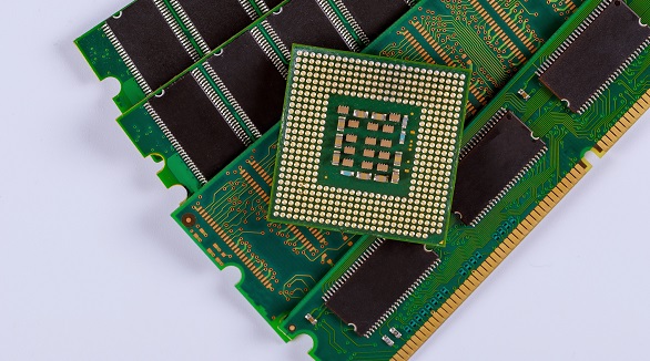
These two terms, SMT and SMD, are interchangeably used in such a way that misunderstanding is easily possible. Actually, SMT is referring to the technology and the process of placing components onto a PCB, while SMDs are referring to the components themselves. Realization of this difference will make the roles of each in the manufacturing process quite clearer and emphasize how these two interact in effective and efficient PCB production.
The Future and Relevance of SMT
We at PCBX consider SMT as an indispensable technology in the manufacture of modern-day electronics. Its contribution to enabling complexity in design, reducing production times, and allowing for the trend towards miniaturization makes it a necessary technology node in today's fast-moving technological landscape. Significantly, while new technologies are on the horizon, the efficiency, reliability, and adaptability of SMT guarantee its relevance to the industry for a long time to come.
In brief, SMT assembly is a juggling act between precision and efficiency of operations. In order to understand each of the preparation stages through inspection, there is actually so much more in making reliable and advanced electronic products.
Hot Tags:

Contact us

If you can't find what you're looking for, please contact us.
Article
Ensuring BGA soldering quality involves defect prevention, pre-soldering measures, and precise control during SMT assembly and reflow soldering.
 2024/08/20
SMT assembly places components directly on PCBs, enhancing miniaturization, performance, and efficiency. Key steps: solder paste printing, chip mounting, reflow soldering, and inspection.
2024/08/05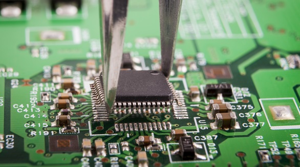
Still, SMT can further feature defects such as solder bridging, cold solder joints, tombstoning, and solder balling. Grasping the very common faults and their solutions is the key toward effective PCB assembly and reducing SMT errors—very much in line with the trend toward PCB miniaturization and higher component density.
2024/07/29