- Products & Capabilities

- About
- Resources
The Ultimate Guide to Thermal Design Principles for PCBs


Thermal management is all about more than just keeping the temperature of electronic systems and printed circuit boards low. It has been a key issue related to reliability and performance. Of the very basic fundamentals that would be studied in the field, some are concerned with methods of heat transfer. These are through conduction, convection, and radiation. The methods of cooling include natural cooling, forced-air cooling, fluid cooling, and evaporation cooling. Appropriate thermal design rules shall be followed wherein the chosen materials provide optimum thermal conductivity and the components of a system are so laid out that no hot-spotting will take place. Thermal analysis becomes critical in pointing out heat-related issues and optimizing the design. It thus minimizes failure rates and enhances stability and functionality of the electronic systems through comprehensive thermal management.
It's estimated that over half of the electronic components fail due to the high stress caused by the thermal environment. In recent years, with the trend of large-scale and hyper-scale integrated circuits and surface mount technology, a wide range of devices and electronic products have started to embrace directions for development toward miniaturization, high density, and high reliability; accordingly, there is an increasingly higher requirement for thermal performance in electronic systems. Natively born with the advent of electronic products, thermal management forms the basis for determining both the performance and functions of an electronic system.
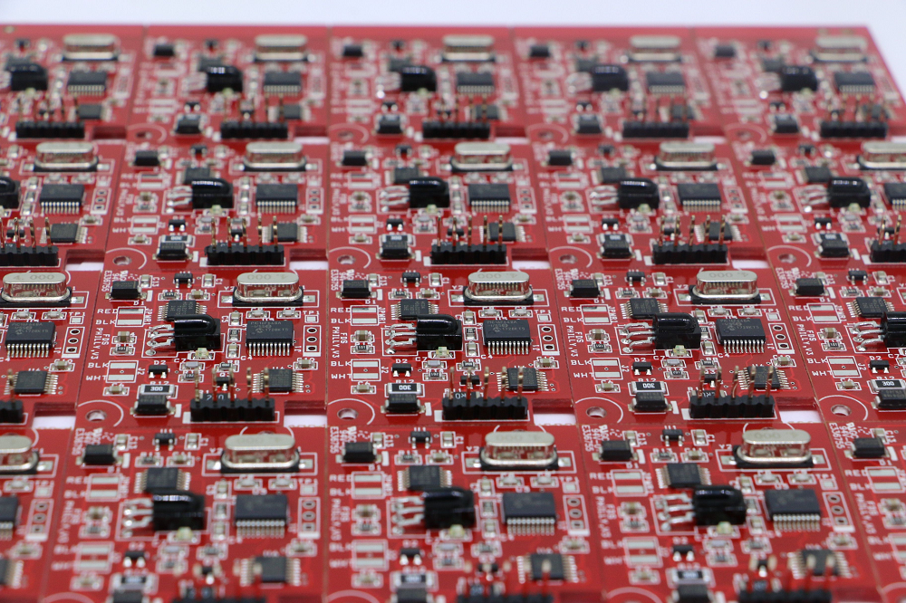
Ranking high in performance, an electronic system with a rationalized design of printed circuit boards seems to be its backbone. If it partially or fails to meet the thermal requirements in the design of a printed circuit board, then damage or even failure risk is certain to be incurred by the electronics. The integrity of circuit modules is ever-improving, with large applications of ICs and MCM, which are conducive to improving the assembly density of components right after. Then it leads to a higher density of heat flux on PCBs. Besides correct and reasonable layout and routing, high-quality PCBs depend on high thermal reliability for safe operation. Therefore, it is very important to establish comprehensive rules for thermal dissipation and analysis on PCBs. Starting with start-up thermal design principles, this paper introduces some engineer-friendly thermal design rules for handy application by electronics designers for their jobs.
The Basic Principles of Thermal Design
The thermal design is based on the basic theory of heat transfer and fluid mechanics. With temperature differences, it can cause heat transfer from a high-temperature zone to a low-temperature zone. There are three ways to enable heat transfer: heat conduction, heat convection, and heat radiation.
The formula of heat transfer is given as φ=KAΔt, where φ is the quantity of heat transferred whose unit is W, K is the coefficient of thermal transmission whose unit is W/(m2 x K), A is the surface area of heat transmission whose unit is m2, and Δt is the temperature difference between thermal fluid and cold fluid whose unit is K.
The thermal design of PCBs is defined as a process in which the thermal resistance from the heat source to the heat consumption space, through cooling measures of thermal transmission attributes, controls the density of heat fluids within an acceptable range. Valid thermal design measures shall be taken for the reliability of this aspect from the following perspectives:
- natural cooling, which conducts heat without external strength. It includes heat conduction, radiation heat transfer, and natural convection transfer.
- Forced air cooling. A stream of cooling air is created through the electronic devices or components by a ventilator or ram-air and transfers heat from the heat source to a heat sink.
- Fluid cooling. There are two ways for cooling using fluid:
- Direct fluid cooling refers to the process during which components are directly soaked into the fluid coolant.
- Indirect fluid cooling refers to the process during which components are not directly in touch with fluid coolant. However, cooling is carried out through a heat exchanger or cold plate.
- Evaporation cooling. Currently, it's the most effective heat conduction method. Thermal transmission is obtained by the ebullition of the cooling medium.
- Other types of cooling: thermotube, cold plate, thermoelectric refrigeration.
Proper thermal design measures can be made by the actual conditions in a practical operation environment regarding temperature, humidity, atmospheric pressure, dust, and other factors; thermal fluid density on board; power volume density and total power consumption; surface area and volume; heat sink; and other special conditions to make sure there is an even distribution of temperature and that the temperature rise remains within a regulated, limited value.
Thermal Design Rules
The general purpose of thermal design is to keep the temperature of all of the electronic components mounted on circuit boards within a product in a specified range so that electrical performance remains stable, electrical parameter temperature drifts are avoided or minimized, basic failure of components is at its minimum, and the temperature in the operation environment would not be too hot above the maximum allowable temperature. This paper expounds on the thermal design rules of printed circuit boards from the following perspectives: the use of components on a PCB, thermal design, and assembly of components, and the layout of a PCB.
a. Use of Electronic Components
1). How do you control the working temperature of components?
Temperature is the first element that affects component performance and failure rate. These have to establish the highest allowable working temperature and power consumption about the required level of reliability and distributed failure rate of any component. Table 1 gives the values of the allowable maximum surface temperature of components from a reliability point of view in thermal design.
| Components | Max. Surface Temp/°C | Components | Max. Surface Temp/°C |
|---|---|---|---|
| Transformer, choke | 95 | Ceramic capacitor | 80-85 |
| Metal film resistor | 100 | Glass ceramic capacitor | 200 |
| Carbon-film resistor | 120 | Silicon transistor | 150-200 |
| Palladium-film resistor | 200 | Germanium transistor | 70-90 |
| Pressed wire wound resistor | 150 | Vacuum tube | 15-200 |
| Printed resistor | 85 | CMOS fully sealed flat package | 125 |
| Painting wire wound resistor | 225 | Ceramic DIP, black porcelain DIP | / |
| Paper capacitor | 75-85 | CMOS plastic DIP | 85 |
| Film capacitor | 60-130 | TTL small-scale IC | 25-125 |
| Mica capacitor | 70-120 | TTL middle-scale IC | 70-85 |
2). How can component junction temperature be controlled?
The junction temperature of a component is determined by its self-power consumption, amount of internal thermal resistance, and ambient temperature. Therefore, measures for keeping the junction temperature of a device within the allowable range should include:
- selection of components with low internal thermal resistance
- Use of derating to lower the temperature rise.
- Circuits, particularly those that involve power components, should be based on detailed thermal design for reliability, and the guidelines for this are charted in a standard manual.
3). How does one design derating when components are used?
According to the needs, derating design can be realized in practical use to make components work in the below-rated parameter condition, such as power voltage or current, which will dramatically reduce temperature rise and failure rate.
b. PCB Thermal Design Rules
The vertical installation of PCB helps in dissipating heat and the distance between boards shall be at least 20mm. Some of the thermal design rules for boards include:
1). Material with the ability to resist high temperatures and high conduction parameters was picked up as the substrate material for PCBs. For circuits with great power and density, substrate materials such as aluminum base and ceramic can be used owing to their low thermal resistance. PCBX is fully capable of manufacturing PCBs with those substrate materials. You may send your PCB files along with quantity requirements on this page for aluminum-based and ceramic-based PCB quotations.
2). The multi-layer structure is best for thermal dissipation from a PCB.
3). Conduction ability of heat for Circuit Boards: Boards dissipating heat are the best for betterment. In the case of a multi-layer PCB, a Metal-core board can be applied to obtain fine heat dissipation among boards, supporting devices, and heat-dissipating devices. Coating and encapsulating material can be used as needed to accelerate thermal transmission to supporting devices or heat-dissipating devices.
4). The use of a busbar increases the heat-dissipation capacity of the PCB, and it can be used as an excellent radiator. After all, adding this feature to a printed circuit board can improve anti-interference performance.
5). To improve the thermal dissipation ability of PCBs, the foil of metal should have a big thickness, and the inner conductor should use metal foil with a large area. Besides, the width of the ground line should be increased properly besides the reason ground lines with big areas can both improve the ability of anti-interference and the dissipation of heat capacity.
c. Component Assembly and PCB Layout
The component layout is rather critical for thermal performance in PCBs, particularly in vertically mounted PCBs. The component mounting orientation shall follow the coolant flow characteristics to provide coolant with minimal resistance. Rules applying to components at the level of assembly and layout include:
1). On products with free convection air cooling methods, it's best for ICs or other components in a lengthwise arrangement, as is shown in the example below in Figure 2. On products with forced air cooling methods, ICs or other components should be arranged in an elongated arrangement; refer to Figure 3 below for an example.
2). The components on the same PCB should be classified and placed according to their heat productivity and dissipation level. Elements such as small-signal transistors, small integrated circuits, electrolytic capacitors, and others that have a low level of heat production or heat resistance should be placed at the entrance, while those like frequency transistors, large-scale integrated circuits, and others with a high level of heat productivity or heat resistance should be placed at the exit. Components with small temperature drifts, liquid medium capacitors, and small signal amplifiers should be located at the periphery of the heat source.
3). In the horizontal direction, components with high frequencies should be placed on the PCB edges to decrease the heat transmission path. In the vertical direction, components with high frequencies should be placed as close as possible to the PCB tops to minimize their interference with the temperatures of other components.
4). Components sensitive to temperature shall be placed in the least hot part of an article; they shall not be positioned directly above components developing heat. Generally, they shall be placed well away from components developing heat or shall be kept separate therefrom.
5). The components that consume the most power and, at the same time, generate the most heat should be situated toward the best place for heat dissipation. Components with a high temperature should never be situated in the corner or at the edge unless there are radiators arranged around them. Relatively large components should be picked up for power resistors, and enough space for heat dissipation should be left during the PCB layout.
6). Uniform distribution of power on PCBs for the sake of keeping balance and conformity and avoiding concentration of heat points. Attaining strict uniformity is rather hard, but it is necessary to avoid areas with extremely high power to stop the over-heated points from breaking the normal operation of the whole circuit.
7). Flow Design Complete consideration must be given to the airflow path in the design of the PCB, and the arrangement of the components should be done sensibly. Air flows towards a place with less resistance, so relatively large air spaces should be avoided when arranging components over the PCBs.
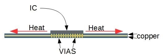
8). Thermal assembly technology should be practiced on circuit boards to achieve a relatively good heat transmission effect. For example, more than 50% of the heat generated by components like ICs and microprocessors is transmitted to the PCBs by the currents passing through their leads. This should be assured by the fact that the holes are metal-plating holes for their assembly. These components can also be affixed directly to thermal conduction sticks or boards to ease the thermal resistance brought about by the components.
9). The thermal resistance in the connections between the components, which possess high thermal dissipation, and the PCBs should be reduced to the extreme. Some heat conduction material under the chip will be allowed, and the heat dissipation of the components in the contact area should be kept to cater to the requirement of heat attributes.
10). The pins of components should be shortened in the connective components and PCBs. When selecting components with high power consumption, the conductivity of the lead material should be considered. It would be better to choose component leads with larger cross sections and, if possible, the most pins.
d. Other Requirements
1). Component Package: component package type and heat conduction rate should be taken into consideration during PCB thermal design. A heat conduction path shall be provided between the substrate and component package, and air breaks shall be avoided on a heat conduction path.
2). The technique method: local high temperatures can be caused in areas with components on both sides of the board. Some fine copper can be added to the soldering paste to change the heat dissipation conditions; the solder points will rise to a certain height under the components. An air space is increased between components and a PCB so that thermal convection can be improved.
3). Heat Dissipation Holes: Some heat dissipation holes and blind holes can be set on the PCB to increase the heat dissipation area, decrease thermal resistance, and raise the power density of the PCB.
Thermal Analysis
The numerical computation methods of thermal analysis based on computational heat transfer mainly include the finite difference method, the finite element method, and the boundary element method and refer to the processes of simplifying modules, establishing math modules, solving nonlinear equations, making and adjusting analytical procedures, and the computation, measurement, and testing of thermal parameters.
As a fundamental aspect of thermal design, thermal analysis is an important method for evaluating the importance of thermal design. Thermal analysis of a PCB refers to setting up a thermal module of components, setting simulation control parameters in line with the structure and raw material, package type of components, and operating environment of a PCB to get values estimated for thermal behaviors. Thermal analysis is done at the concept phase, before the layout stage, and throughout the entire process of designing a PCB.
It can also return values of component temperature, board temperature, and airflow temperature from thermal analysis, showing thermal characteristics of PCBs through colored pictures and temperature isotherm visual charts or otherwise in data form.
According to the result of thermal analysis, it is possible to find out the thermal problems of PCB quickly, take proper timely measures to eliminate high-temperature dense areas that will determine the heat conduction path, optimize the position of key components, and change the shape and size of radiators to fully use the rate of heat dissipation.
PCBX Has Rich Experience in Manufacturing PCBs with Advanced Features
Founded in 2005, PCBX has been manufacturing circuit boards for clients from 120+ countries. Manufactured PCBs are applied in almost all industries. You may reach out to us to discuss your custom PCB project here.
Hot Tags:

Contact us

If you can't find what you're looking for, please contact us.
Article
Still, SMT can further feature defects such as solder bridging, cold solder joints, tombstoning, and solder balling. Grasping the very common faults and their solutions is the key toward effective PCB assembly and reducing SMT errors—very much in line with the trend toward PCB miniaturization and higher component density.
 2024/07/29
The article is developed concerning the breakthrough of integrated circuits and the need for custom PCBs in some electronic products. It enumerates ten golden rules in conducting PCB layout design and manufacturing: grid selection, routing, power layers, component placement, panel duplication, component value combination, frequent DRC, flexible silkscreen use, decoupling capacitors, and pre-production parameter checks. These rules provide for the optimum design and manufacturing of a PCB.
2024/07/25
Most electronic circuits are mounted on PCBs, or Printed Circuit Boards, which provide mechanical support and electrical interconnection of electronic components. There are, however, special applications that involve the use of single and double-sided PCBs, multi-layer PCBs, or even rigid and flexible PCBs with aluminum backing, targeting medical, industrial, auto, and aerospace industries. They may use materials such as fiberglass, epoxy, aluminum, and others.
2024/07/25